MC56F8037EVM Freescale Semiconductor, MC56F8037EVM Datasheet - Page 109
MC56F8037EVM
Manufacturer Part Number
MC56F8037EVM
Description
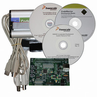
BOARD EVAL FOR MC56F8037
Manufacturer
Freescale Semiconductor
Type
MCUr
Datasheet
1.MC56F8037EVM.pdf
(180 pages)
Specifications of MC56F8037EVM
Contents
Board, Cables, CD, Debugger
Silicon Manufacturer
Freescale
Core Architecture
56800/E
Core Sub-architecture
56800/E
Silicon Core Number
MC56F
Silicon Family Name
MC56F80xx
Kit Contents
MC56F8037EVM, USB-JTAG Adapter, Cables, CD
Rohs Compliant
Yes
For Use With/related Products
MC56F8037
Lead Free Status / RoHS Status
Lead free / RoHS Compliant
Available stocks
Company
Part Number
Manufacturer
Quantity
Price
Company:

Part Number:
MC56F8037EVM
Manufacturer:
Freescale Semiconductor
Quantity:
135


6.3.12.6
6.3.12.7
6.3.12.8
6.3.12.9
6.3.12.10 Quad Timer A, Channel 3 Clock Stop Disable (TA3_SD)—Bit 3
6.3.12.11 Quad Timer A, Channel 2 Clock Stop Disable (TA2_SD)—Bit 2
6.3.12.12 Quad Timer A, Channel 1 Clock Stop Disable (TA1_SD)—Bit 1
6.3.12.13 Quad Timer A, Channel 0 Clock Stop Disable (TA0_SD)—Bit 0
6.3.13
In I/O short address mode, the instruction specifies only 6 LSBs of the effective address; the upper 18 bits
are “hard coded” to a specific area of memory. This scheme allows efficient access to a 64-location area
in peripheral space with single word instruction. Short address location registers specify the upper 18 bits
Freescale Semiconductor
•
•
•
•
•
•
•
•
•
•
•
•
•
•
•
•
0 = The clock is disabled during Stop mode
1 = The clock is enabled during Stop mode if the clock to this peripheral is enabled in the SIM_PCE1
register
0 = The clock is disabled during Stop mode
1 = The clock is enabled during Stop mode if the clock to this peripheral is enabled in the SIM_PCE1
register
0 = The clock is disabled during Stop mode
1 = The clock is enabled during Stop mode if the clock to this peripheral is enabled in the SIM_PCE1
register
0 = The clock is disabled during Stop mode
1 = The clock is enabled during Stop mode if the clock to this peripheral is enabled in the SIM_PCE1
register
0 = The clock is disabled during Stop mode
1 = The clock is enabled during Stop mode if the clock to this peripheral is enabled in the SIM_PCE1
register
0 = The clock is disabled during Stop mode
1 = The clock is enabled during Stop mode if the clock to this peripheral is enabled in the SIM_PCE1
register
0 = The clock is disabled during Stop mode
1 = The clock is enabled during Stop mode if the clock to this peripheral is enabled in the SIM_PCE1
register
0 = The clock is disabled during Stop mode
1 = The clock is enabled during Stop mode if the clock to this peripheral is enabled in the SIM_PCE1
register
I/O Short Address Location Register High (SIM_IOSAHI)
Quad Timer B, Channel 3 Clock Stop Disable (TB3_SD)—Bit 7
Quad Timer B, Channel 2 Clock Stop Disable (TB2_SD)—Bit 6
Quad Timer B, Channel 1 Clock Stop Disable (TB1_SD)—Bit 5
Quad Timer B, Channel 0 Clock Stop Disable (TB0_SD)—Bit 4
56F8037/56F8027 Data Sheet, Rev. 7
Register Descriptions
109
Related parts for MC56F8037EVM
Image
Part Number
Description
Manufacturer
Datasheet
Request
R

Part Number:
Description:
Manufacturer:
Freescale Semiconductor, Inc
Datasheet:
Part Number:
Description:
Manufacturer:
Freescale Semiconductor, Inc
Datasheet:
Part Number:
Description:
Manufacturer:
Freescale Semiconductor, Inc
Datasheet:
Part Number:
Description:
Manufacturer:
Freescale Semiconductor, Inc
Datasheet:
Part Number:
Description:
Manufacturer:
Freescale Semiconductor, Inc
Datasheet:
Part Number:
Description:
Manufacturer:
Freescale Semiconductor, Inc
Datasheet:
Part Number:
Description:
Manufacturer:
Freescale Semiconductor, Inc
Datasheet:
Part Number:
Description:
Manufacturer:
Freescale Semiconductor, Inc
Datasheet:
Part Number:
Description:
Manufacturer:
Freescale Semiconductor, Inc
Datasheet:
Part Number:
Description:
Manufacturer:
Freescale Semiconductor, Inc
Datasheet:
Part Number:
Description:
Manufacturer:
Freescale Semiconductor, Inc
Datasheet:
Part Number:
Description:
Manufacturer:
Freescale Semiconductor, Inc
Datasheet:
Part Number:
Description:
Manufacturer:
Freescale Semiconductor, Inc
Datasheet:
Part Number:
Description:
Manufacturer:
Freescale Semiconductor, Inc
Datasheet:
Part Number:
Description:
Manufacturer:
Freescale Semiconductor, Inc
Datasheet: