EVB9303 SMSC, EVB9303 Datasheet - Page 30
EVB9303
Manufacturer Part Number
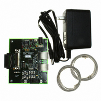
EVB9303
Description
EVALUATION BOARD FOR LAN9303
Manufacturer
SMSC
Specifications of EVB9303
Main Purpose
Interface, Ethernet
Embedded
No
Utilized Ic / Part
LAN9303
Primary Attributes
3 Ports, 100BASE-TX/10BASE-T, Managed
Secondary Attributes
Full Duplex and HP Auto-MDIX Support, 10BASE-T and 100BASE-TX
Lead Free Status / Rohs Status
Lead free / RoHS Compliant
Other names
638-1095


Revision 1.4 (07-07-10)
PINS
NUM
1
1
Reference
Port 0 MII
Port 0 MII
Collision
NAME
Output
Clock
P0_OUTCLK
SYMBOL
P0_COL
Table 3.4 Port 0 MII/RMII Pins (continued)
Small Form Factor Three Port 10/100 Managed Ethernet Switch with Single MII/RMII/Turbo MII
DATASHEET
BUFFER
O12/O16
IS/O12/
TYPE
(PD)
(PD)
(PU)
O16
O8
IS
IS
-
30
MII MAC Mode: This pin is an input and is used as
the reference clock for the P0_OUTD[3:0] and
P0_OUTDV pins. It is connected to the transmit
clock of the external PHY.
MII PHY Mode: This pin is an output and is used
as the reference clock for the P0_OUT[3:0] and
P0_OUTDV pins. It is connected to the receive
clock of the external MAC. The output driver is
disabled when the
the
(VPHY_BASIC_CTRL). When operating at
200MBps, the choice of drive strength is based on
the setting of the
in the
(VPHY_SPECIAL_CONTROL_STATUS). A low
selects a 12 mA drive, while a high selects a 16 mA
drive. A series terminating resistor is recommended
for the best PCB signal integrity.
RMII PHY Mode: This pin is an input or an output
running at 50 MHz and is used as the reference
clock for the P0_IND[1:0], P0_INDV,
P0_OUTD[1:0], and P0_OUTDV pins. The choice
of input verses output is based on the setting of the
RMII Clock Direction
Control/Status Register
(VPHY_SPECIAL_CONTROL_STATUS). A low
selects P0_OUTCLK as an input and a high selects
P0_OUTCLK as an output.
As an input, the pull-down is normally enabled. The
input buffer and pull-down are disabled when the
Isolate (VPHY_ISO)
Basic Control Register
As an output, the input buffer and pull-down are
disabled. The choice of drive strength is based on
the MII Virtual PHY
bit. A low selects a 12 mA drive, while a high
selects a 16 mA drive. The output driver is disabled
when the
Virtual PHY Basic Control Register
(VPHY_BASIC_CTRL). A series terminating
resistor is recommended for the best PCB signal
integrity.
MII MAC Mode: This pin is an input from the
external PHY and indicates a collision event.
MII PHY Mode: This pin is an output to the external
MAC indicating a collision event. The output driver
is disabled when the
in the
(VPHY_BASIC_CTRL).
RMII PHY Mode: This pin is not used.
Virtual PHY Basic Control Register
Virtual PHY Special Control/Status Register
Virtual PHY Basic Control Register
Isolate (VPHY_ISO)
RMII/Turbo MII Clock Strength
DESCRIPTION
Isolate (VPHY_ISO)
RMII/Turbo MII Clock Strength
bit is set in the
Isolate (VPHY_ISO)
bit in the
(VPHY_BASIC_CTRL).
SMSC LAN9303/LAN9303i
Virtual PHY Special
bit is set in the
Virtual PHY
bit is set in
bit is set
Datasheet
bit
Related parts for EVB9303
Image
Part Number
Description
Manufacturer
Datasheet
Request
R


Part Number:
Description:
FAST ETHERNET PHYSICAL LAYER DEVICE
Manufacturer:
SMSC Corporation
Datasheet:
Part Number:
Description:
357-036-542-201 CARDEDGE 36POS DL .156 BLK LOPRO
Manufacturer:
SMSC Corporation
Datasheet:
Part Number:
Description:
357-036-542-201 CARDEDGE 36POS DL .156 BLK LOPRO
Manufacturer:
SMSC Corporation
Datasheet:
Part Number:
Description:
357-036-542-201 CARDEDGE 36POS DL .156 BLK LOPRO
Manufacturer:
SMSC Corporation
Datasheet:
Part Number:
Description:
4-PORT USB2.0 HUB CONTROLLER
Manufacturer:
SMSC Corporation
Datasheet:
Part Number:
Description:
Manufacturer:
SMSC Corporation
Datasheet:
Part Number:
Description:
Manufacturer:
SMSC Corporation
Datasheet:
Part Number:
Description:
FDC37C672ENHANCED SUPER I/O CONTROLLER WITH FAST IR
Manufacturer:
SMSC Corporation
Datasheet:
Part Number:
Description:
COM90C66LJPARCNET Controller/Transceiver with AT Interface and On-Chip RAM
Manufacturer:
SMSC Corporation
Datasheet:
Part Number:
Description:
Manufacturer:
SMSC Corporation
Datasheet:
Part Number:
Description:
Manufacturer:
SMSC Corporation
Datasheet:
Part Number:
Description:
Manufacturer:
SMSC Corporation
Datasheet:
Part Number:
Description:
Manufacturer:
SMSC Corporation
Datasheet: