EVB9303 SMSC, EVB9303 Datasheet - Page 109
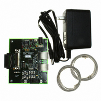
EVB9303
Manufacturer Part Number
EVB9303
Description
EVALUATION BOARD FOR LAN9303
Manufacturer
SMSC
Specifications of EVB9303
Main Purpose
Interface, Ethernet
Embedded
No
Utilized Ic / Part
LAN9303
Primary Attributes
3 Ports, 100BASE-TX/10BASE-T, Managed
Secondary Attributes
Full Duplex and HP Auto-MDIX Support, 10BASE-T and 100BASE-TX
Lead Free Status / Rohs Status
Lead free / RoHS Compliant
Other names
638-1095


Small Form Factor Three Port 10/100 Managed Ethernet Switch with Single MII/RMII/Turbo MII
Datasheet
SMSC LAN9303/LAN9303i
8.3.3
8.3.4
C
C
A
K
A
K
S 1 0 1 0
S 1 0 1 0
I
Following the device addressing, data bytes may be read sequentially from the EEPROM by outputting
a start condition and control byte with a control code of 1010b, chip/block select bits as described in
Section
bits of data. If the EEPROM slave fails to send an acknowledge, then the sequence is aborted and
the
(E2P_CMD)
next 8-bits of data. This continues until the last desired byte is read, at which point the I
sends a no-acknowledge, followed by a stop condition.
Figure 8.3
Sequential reads are used by the EEPROM Loader. Refer to
additional information.
For a register level description of a read operation, refer to
Controller Operation," on page
I
Following the device addressing, a data byte may be written to the EEPROM by outputting the data
after receiving the acknowledge from the EEPROM. The data byte is acknowledged by the EEPROM
slave and the I
send an acknowledge, then the sequence is aborted and the
(EPC_TIMEOUT)
Following the data byte write cycle, the I
write is finished. After meeting the minimum bus free time, a start condition is sent followed by a control
byte with a control code of 1010b, chip/block select bits low, and the R/~W bit low. If the EEPROM is
finished with the byte write, it will respond with an acknowledge. Otherwise, it will respond with a no-
acknowledge and the I
occur within 30mS, a time-out occurs. The check for timeout is only performed following each no-
acknowledge, since it may be possible that the EEPROM write finished before the timeout but the
30mS expired before the poll was performed (due to the bus being used by another master).
Once the I
a stop condition, which will place the EEPROM into standby.
2
2
C EEPROM Sequential Byte Reads
C EEPROM Byte Writes
EEPROM Controller Timeout (EPC_TIMEOUT)
Control Byte
Control Byte
Chip / Block
Chip / Block
Select Bits
Select Bits
8.3.1, and the R/~W bit high. The EEPROM will respond with an acknowledge, followed by 8-
illustrates typical I
A
1
0
0 0 0
2
C master receives the acknowledge, it concludes by sending a start condition, followed by
is set. The I
A
9
A
2
8
C master finishes the write cycle with a stop condition. If the EEPROM slave fails to
1
1
R/~W
R/~W
bit in the
Figure 8.4 I
A
C
K
A
C
K
D
D
7
7
2
C master will issue a stop and repeat the poll. If the acknowledge does not
2
D
6
D
6
Double Byte Addressing Sequential Reads
Single Byte Addressing Sequential Reads
C master then sends an acknowledge, and the EEPROM responds with the
Data Byte
Data Byte
D
5
D
5
EEPROM Command Register (E2P_CMD)
2
C EEPROM sequential byte reads for single and double byte addressing.
D
D
4
4
2
111.
C EEPROM Sequential Byte Reads
D
3
D
3
D
D
2
2
DATASHEET
D
D
1
1
D
0
D
0
2
A
C
K
A
C
K
C master will poll the EEPROM to determine when the byte
109
D
7
D
7
D
6
D
6
Data Byte
Data Byte
D
D
5
5
D
D
4
4
D
3
D
3
D
2
D
2
bit in the
D
1
D
1
D
0
D
0
A
C
K
A
C
K
Section 8.3.7, "I2C Master EEPROM
...
...
Section 8.4, "EEPROM Loader"
D
7
D
7
EEPROM Command Register
EEPROM Controller Timeout
D
D
6
6
is set.
Data Byte
Data Byte
D
5
D
5
D
4
D
4
D
D
3
3
D
2
D
2
Revision 1.4 (07-07-10)
D
D
1
1
D
D
0
0
A
C
K
A
C
K
P
P
2
C master
for
Related parts for EVB9303
Image
Part Number
Description
Manufacturer
Datasheet
Request
R


Part Number:
Description:
FAST ETHERNET PHYSICAL LAYER DEVICE
Manufacturer:
SMSC Corporation
Datasheet:
Part Number:
Description:
357-036-542-201 CARDEDGE 36POS DL .156 BLK LOPRO
Manufacturer:
SMSC Corporation
Datasheet:
Part Number:
Description:
357-036-542-201 CARDEDGE 36POS DL .156 BLK LOPRO
Manufacturer:
SMSC Corporation
Datasheet:
Part Number:
Description:
357-036-542-201 CARDEDGE 36POS DL .156 BLK LOPRO
Manufacturer:
SMSC Corporation
Datasheet:
Part Number:
Description:
4-PORT USB2.0 HUB CONTROLLER
Manufacturer:
SMSC Corporation
Datasheet:
Part Number:
Description:
Manufacturer:
SMSC Corporation
Datasheet:
Part Number:
Description:
Manufacturer:
SMSC Corporation
Datasheet:
Part Number:
Description:
FDC37C672ENHANCED SUPER I/O CONTROLLER WITH FAST IR
Manufacturer:
SMSC Corporation
Datasheet:
Part Number:
Description:
COM90C66LJPARCNET Controller/Transceiver with AT Interface and On-Chip RAM
Manufacturer:
SMSC Corporation
Datasheet:
Part Number:
Description:
Manufacturer:
SMSC Corporation
Datasheet:
Part Number:
Description:
Manufacturer:
SMSC Corporation
Datasheet:
Part Number:
Description:
Manufacturer:
SMSC Corporation
Datasheet:
Part Number:
Description:
Manufacturer:
SMSC Corporation
Datasheet: