EVB9303 SMSC, EVB9303 Datasheet - Page 106
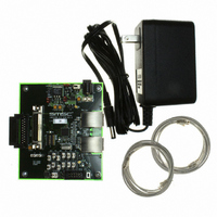
EVB9303
Manufacturer Part Number
EVB9303
Description
EVALUATION BOARD FOR LAN9303
Manufacturer
SMSC
Specifications of EVB9303
Main Purpose
Interface, Ethernet
Embedded
No
Utilized Ic / Part
LAN9303
Primary Attributes
3 Ports, 100BASE-TX/10BASE-T, Managed
Secondary Attributes
Full Duplex and HP Auto-MDIX Support, 10BASE-T and 100BASE-TX
Lead Free Status / Rohs Status
Lead free / RoHS Compliant
Other names
638-1095


Chapter 8 Serial Management
Revision 1.4 (07-07-10)
8.1
8.2
This chapter details the serial management functionality provided by the device, which includes the
EEPROM I
The I
with the system register bus and the EEPROM Loader. Multiple sizes of external EEPROMs are
supported. Configuration of the EEPROM size is accomplished via the
configuration strap. Various commands are supported for EEPROM access, allowing for the storage
and retrieval of static data. The I
The EEPROM Loader provides the automatic loading of configuration settings from the EEPROM into
the device at reset. The EEPROM Loader module interfaces to the EEPROM Controller, Ethernet
PHYs, and the system CSRs.
The I
CSRs. The I
condition detection, data bit transmission/reception, and acknowledge generation/reception), handles
the slave command protocol, and performs system register reads and writes. The I
conforms to the NXP I
I
device that receives data is defined as a receiver. The bus is controlled by a master which generates
the EE_SCL clock, controls bus access, and generates the start and stop conditions. Either the master
or slave may operate as a transmitter or receiver as determined by the master.
The device implements an I
by a management master. Both the clock and data signals have digital input filters that reject pulses
that are less than 100nS. The I
data pin is driven low when either interface sends a low, emulating the wired-AND function of the I
bus. Since the slave interface never drives the clock pin, the wired-AND is not necessary.
The following bus states exist:
Functional Overview
I
2
2
C is a bi-directional 2-wire data protocol. A device that sends data is defined as a transmitter and a
C Overview
Idle: Both EE_SDA/SDA and EE_SCL/SCL are high when the bus is idle.
Start & Stop Conditions: A start condition is defined as a high to low transition on the EE_ SDA
line while EE_ SCL is high. A stop condition is defined as a low to high transition on the EE_SDA
line while EE_SCL is high. The bus is considered to be busy following a start condition and is
considered free 4.7uS/1.3uS (for 100KHz and 400KHz operation, respectively) following a stop
condition. The bus stays busy following a repeated start condition (instead of a stop condition).
Starts and repeated starts are otherwise functionally equivalent.
Data Valid: Data is valid, following the start condition, when EE_SDA is stable while EE_SCL is
high. Data can only be changed while the clock is low. There is one valid bit per clock pulse. Every
byte must be 8 bits long and is transmitted msb first.
Acknowledge: Each byte of data is followed by an acknowledge bit. The master generates a ninth
clock pulse for the acknowledge bit. The transmitter releases EE_SDA/SDA (high). The receiver
drives EE_SDA/SDA low so that it remains valid during the high period of the clock, taking into
account the setup and hold times. The receiver may be the master or the slave depending on the
direction of the data. Typically the receiver acknowledges each byte. If the master is the receiver,
it does not generate an acknowledge on the last byte of a transfer. This informs the slave to not
drive the next byte of data so that the master may generate a stop or repeated start condition.
2
2
C EEPROM controller is an I
C slave controller can be used for CPU serial management and allow CPU access to all system
2
C master, EEPROM Loader, and I
2
C slave controller implements the low level I
2
C-Bus Specification .
2
C master for accessing an external EEPROM and an I
Small Form Factor Three Port 10/100 Managed Ethernet Switch with Single MII/RMII/Turbo MII
2
C Master and the I
2
C interface conforms to the NXP I
DATASHEET
2
C master module which interfaces an optional external EEPROM
106
2
C slave controller.
2
C Slave Serial interfaces share common pins. The
2
C slave serial interface (start and stop
2
C-Bus Specification .
SMSC LAN9303/LAN9303i
eeprom_size_strap
2
2
C slave for control
C slave controller
Datasheet
2
C
Related parts for EVB9303
Image
Part Number
Description
Manufacturer
Datasheet
Request
R


Part Number:
Description:
FAST ETHERNET PHYSICAL LAYER DEVICE
Manufacturer:
SMSC Corporation
Datasheet:
Part Number:
Description:
357-036-542-201 CARDEDGE 36POS DL .156 BLK LOPRO
Manufacturer:
SMSC Corporation
Datasheet:
Part Number:
Description:
357-036-542-201 CARDEDGE 36POS DL .156 BLK LOPRO
Manufacturer:
SMSC Corporation
Datasheet:
Part Number:
Description:
357-036-542-201 CARDEDGE 36POS DL .156 BLK LOPRO
Manufacturer:
SMSC Corporation
Datasheet:
Part Number:
Description:
4-PORT USB2.0 HUB CONTROLLER
Manufacturer:
SMSC Corporation
Datasheet:
Part Number:
Description:
Manufacturer:
SMSC Corporation
Datasheet:
Part Number:
Description:
Manufacturer:
SMSC Corporation
Datasheet:
Part Number:
Description:
FDC37C672ENHANCED SUPER I/O CONTROLLER WITH FAST IR
Manufacturer:
SMSC Corporation
Datasheet:
Part Number:
Description:
COM90C66LJPARCNET Controller/Transceiver with AT Interface and On-Chip RAM
Manufacturer:
SMSC Corporation
Datasheet:
Part Number:
Description:
Manufacturer:
SMSC Corporation
Datasheet:
Part Number:
Description:
Manufacturer:
SMSC Corporation
Datasheet:
Part Number:
Description:
Manufacturer:
SMSC Corporation
Datasheet:
Part Number:
Description:
Manufacturer:
SMSC Corporation
Datasheet: