EVB9303 SMSC, EVB9303 Datasheet
EVB9303
Specifications of EVB9303


Related parts for EVB9303


EVB9303 Summary of contents
Page 1
... Any and all such uses without prior written approval of an Officer of SMSC and further testing and/or modification will be fully at the risk of the customer. Copies of this document or other SMSC literature, as well as the Terms of Sale Agreement, may be obtained by visiting SMSC’ ...
Page 2
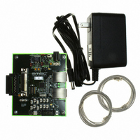
... Ethernet and Fast Ethernet applications. The EVB9303 is an Evaluation Board (EVB) that utilizes the LAN9303 to provide a fully functional three-port single MII/RMII/Turbo MII Ethernet switch. The EVB9303 provides two fully integrated MAC/PHY Ethernet ports (Ports 1 & ...
Page 3
... LAN9303 Evaluation Board User Manual 1.1 References Concepts and material available in the following documents may be helpful when using the EVB9303. DOCUMENT SMSC LAN9303 Datasheet AN8-13 Suggested Magnetics SMSC EVB9303 Evaluation Board Schematic 2 Board Details The following sections describe the various board features, including jumpers, LEDs, test points, system connections, and switches ...
Page 4
... Jumpers JP7 through JP18 set various functions of the LAN9303. They can also be used as GPIOs, LED drivers, or interrupts. When used as LED drivers, as they are on the EVB9303, they are connected a specific way to set the strap value to a “1”, and another way to set the strap value to a “ ...
Page 5
... EEPROM size jumper JP9, JP15 (Note 2.1, Note Note 2.1 Paired jumpers MUST be set identically. Note 2.2 The EVB9303 uses an 8Kx8 EEPROM. Therefore, this jumper MUST be set to 1-2. SMSC LAN9303 SMI master or through EEPROM fields. +3.3V Strap Pulldown R1 332 LED2 ...
Page 6
... C (Default) 1 RESERVED Table 2.5 Jumpers - PHY Port Address 1 2 Set PHY_ADDR to “1” 2.6) 2---3 Set PHY_ADDR to “0” Table 2.6: Table 2.6 PHY_ADDR Settings PORT 1 ADDRESS USER MANUAL 6 LAN9303 Evaluation Board User Manual SETTINGS SETTINGS PORT 2 ADDRESS 2 3 SMSC LAN9303 ...
Page 7
... TP4 Single pin populated gold post GND testpoint GND TP5 2-pin populated IRQ testpoint with GND TP6 Single pin unpopulated P0_DUPLEX TP8 Single pin unpopulated nRST SMSC LAN9303 Table 2.7 LEDs COLOR Green +3.3V power active Green Full-duplex/Collision Port 1 Green Full-duplex/Collision Port 2 ...
Page 8
... This section details the various EVB9303 power, mode, and reset switches. 2.5.1 Power SWITCH S1 SPDT tiny toggle power switch Note: The EVB9303 includes a 2A fuse (F1) to protect from overcurrrent conditions. If this fuse becomes damaged, it can be replaced with a 2A Littlefuse-154002. Revision 1.0 (05-28-09) Table 2.9 System Connections DESCRIPTION 2-pin (1x2) header ...
Page 9
... SMSC LAN9303 Table 2.11 Port 0 Mode Switches DESCRIPTION Sets P0_MODE0 low when closed (on). Otherwise, the signal is pulled-up internally. (Note Sets P0_MODE1 low when closed (on). Otherwise, the signal is pulled-up internally. (Note Sets P0_MODE2 low when closed (on). Otherwise, the signal is pulled-up internally. (Note Sets P0_MODE3 low when closed (on) ...
Page 10
... Reset SWITCH S3 SW pushbutton 2.6 Mechanicals Figure 2.3 details the EVB9303 mechanical dimensions. 0.275 0.240 Ø0.125 Ø0.125 0.240 0.275 Revision 1.0 (05-28-09) Table 2.13 Reset Switch DESCRIPTION Reset: Generates nRST TOP VIEW 3.500 Figure 2.3 EVB9303 Mechanicals USER MANUAL 10 LAN9303 Evaluation Board User Manual FUNCTION 0 ...