EVL6563S-100W STMicroelectronics, EVL6563S-100W Datasheet - Page 27
EVL6563S-100W
Manufacturer Part Number
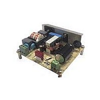
EVL6563S-100W
Description
EVAL BOARD FOR L6563(100W)
Manufacturer
STMicroelectronics
Type
Power Factor Correctionr
Specifications of EVL6563S-100W
Main Purpose
Power Management, Power Factor Correction
Embedded
No
Utilized Ic / Part
L6563
Primary Attributes
100W Power Factor Correction and Preregulator Combination
Secondary Attributes
Transition Mode & Active Tracking Boost Function.
Board Size
90 mm x 83 mm
Maximum Operating Temperature
+ 60 C
Operating Supply Voltage
90 V to 265 V
Product
Power Management Modules
Dimensions
90 mm x 83 mm
Lead Free Status / RoHS Status
Lead free / RoHS Compliant
For Use With/related Products
L6563S
Other names
497-10490


AN3065
6
Figure 35. EVL6563S-100W TM PFC CE peak
EMI filtering and conducted EMI pre-compliance
measurements
The following figures show the peak measurement of the conducted noise at full load and
nominal mains voltages for both mains lines. The limits shown in the diagrams are EN55022
class-B which is the most popular regulation for domestic equipment using a two-wire mains
connection.
It is also useful to remind that typically a PFC produces a significant differential mode noise
with respect to other topologies and therefore in case an additional margin with respect to
the limits is required, we suggest trying to increase the across-the-line (X) capacitors or the
capacitor after the rectifier bridge C5. This will be more effective and cheaper than
increasing the size of the common-mode filter coil that would filter the differential mode
noise by the leakage inductance between the two windings only.
In order to recognize if the circuit is affected by common mode or differential mode noise it is
sufficient to compare the spectrum of phase and neutral line measurements. If the two
measurements are very similar, the noise is almost totally common mode. If there is a
significant difference between the two measurement spectrums, their difference represents
the amount of differential mode noise. Of course to get a reliable comparison the two
measurements have to be done in the same conditions. If the peak measurement is used as
in the figures below, some countermeasures will have to be used, like synchronizing the
sweep of the spectrum analyzer with the input voltage. This is necessary with TM PFC
having a switching frequency that is modulated along the sine wave.
Because the differential mode produces the common mode noise by the magnetic field
induced by the current, decreasing the differential mode consequently limits the second one.
measurement at 100 Vac, 50 Hz, full
load, phase
EMI filtering and conducted EMI pre-compliance measurements
Doc ID 16279 Rev 2
Figure 36. EVL6563S-100W TM PFC CE peak
measurement at 100 Vac, 50 Hz, full
load, neutral
27/33
Related parts for EVL6563S-100W
Image
Part Number
Description
Manufacturer
Datasheet
Request
R

Part Number:
Description:
EVAL BOARD FOR L6563(250W)
Manufacturer:
STMicroelectronics
Datasheet:

Part Number:
Description:
EVAL BOARD FOR L6563(400W)
Manufacturer:
STMicroelectronics
Datasheet:

Part Number:
Description:
Power Management Modules & Development Tools Tranisition Mode PFC L6563S EVL Board
Manufacturer:
STMicroelectronics
Datasheet:

Part Number:
Description:
EVAL BOARD L6563 (200W)
Manufacturer:
STMicroelectronics
Datasheet:
Part Number:
Description:
STMicroelectronics [RIPPLE-CARRY BINARY COUNTER/DIVIDERS]
Manufacturer:
STMicroelectronics
Datasheet:
Part Number:
Description:
STMicroelectronics [LIQUID-CRYSTAL DISPLAY DRIVERS]
Manufacturer:
STMicroelectronics
Datasheet:

Part Number:
Description:
BOARD EVAL FOR MEMS SENSORS
Manufacturer:
STMicroelectronics
Datasheet:
Part Number:
Description:
NPN TRANSISTOR POWER MODULE
Manufacturer:
STMicroelectronics
Datasheet:
Part Number:
Description:
TURBOSWITCH ULTRA-FAST HIGH VOLTAGE DIODE
Manufacturer:
STMicroelectronics
Datasheet:
Part Number:
Description:
Manufacturer:
STMicroelectronics
Datasheet:
Part Number:
Description:
DIODE / SCR MODULE
Manufacturer:
STMicroelectronics
Datasheet:
Part Number:
Description:
DIODE / SCR MODULE
Manufacturer:
STMicroelectronics
Datasheet: