EVL6563S-100W STMicroelectronics, EVL6563S-100W Datasheet - Page 23
EVL6563S-100W
Manufacturer Part Number
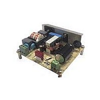
EVL6563S-100W
Description
EVAL BOARD FOR L6563(100W)
Manufacturer
STMicroelectronics
Type
Power Factor Correctionr
Specifications of EVL6563S-100W
Main Purpose
Power Management, Power Factor Correction
Embedded
No
Utilized Ic / Part
L6563
Primary Attributes
100W Power Factor Correction and Preregulator Combination
Secondary Attributes
Transition Mode & Active Tracking Boost Function.
Board Size
90 mm x 83 mm
Maximum Operating Temperature
+ 60 C
Operating Supply Voltage
90 V to 265 V
Product
Power Management Modules
Dimensions
90 mm x 83 mm
Lead Free Status / RoHS Status
Lead free / RoHS Compliant
For Use With/related Products
L6563S
Other names
497-10490


AN3065
4.7
tracking ends and the output voltage becomes constant. If this function is not used, leave
the pin open. The device will regulate at a fixed output voltage.
Power management and housekeeping functions
A special feature of the L6563S is that it facilitates the implementation of the "housekeeping"
circuitry needed to coordinate the operation of the PFC stage with the cascaded DC-DC
converter. The functions implemented by the housekeeping circuitry ensure that transient
conditions like power-up or power-down sequencing or failures of either power stage are
properly handled. The L6563S provides pins to do that.
As already mentioned, one communication line between the L6563S and the PWM
controller of the cascaded DC-DC converter is the PWM_LATCH (pin #8), which is normally
open when the PFC works properly. It goes high if the L6563S loses control of the output
voltage (because of a failure of the control loop) with the aim of latching off the PWM
controller of the cascaded DC-DC converter as well.
A second communication line can be established via the disable function included in the
RUN pin. Typically, this line is used to allow the PWM controller of the cascaded DC-DC
converter to shut down the L6563S in case of light load, in order to minimize the no-load
input consumption of the power supply.
Figure 31. L6563S on/off control by a cascaded converter controller via the PFC_OK
The third communication line is the PWM_STOP (pin #9), which works in conjunction with
the RUN (pin#10). The purpose of the PWM_STOP pin is to inhibit the PWM activity of both
the PFC stage and the cascaded DC-DC converter. The pin is an open collector, normally
open, that goes low if the device is disabled by a voltage lower than 0.8 V on the RUN (pin
#10). It is important to point out that this function works correctly in systems where the PFC
stage is the master and the cascaded DC-DC converter is the slave or, in other words,
where the PFC stage starts first, powers both controllers and enables/disables the operation
of the DC-DC stage. This function is quite flexible and can be used in different ways. In
systems comprising an auxiliary converter and a main converter (e.g. a desktop PC's silver
box or hi-end flatscreen TV or monitor), where the auxiliary converter also powers the
controllers of the main converter, the RUN (pin #10) can be used to start and stop the main
converter. In the simplest case, to enable/disable the PWM controller the PWM_STOP (pin
#9) can be connected to either the output of the error amplifier or, if the chip is provided with
it, to its soft-start pin.
or RUN pin
Doc ID 16279 Rev 2
Test results and significant waveforms
23/33
Related parts for EVL6563S-100W
Image
Part Number
Description
Manufacturer
Datasheet
Request
R

Part Number:
Description:
EVAL BOARD FOR L6563(250W)
Manufacturer:
STMicroelectronics
Datasheet:

Part Number:
Description:
EVAL BOARD FOR L6563(400W)
Manufacturer:
STMicroelectronics
Datasheet:

Part Number:
Description:
Power Management Modules & Development Tools Tranisition Mode PFC L6563S EVL Board
Manufacturer:
STMicroelectronics
Datasheet:

Part Number:
Description:
EVAL BOARD L6563 (200W)
Manufacturer:
STMicroelectronics
Datasheet:
Part Number:
Description:
STMicroelectronics [RIPPLE-CARRY BINARY COUNTER/DIVIDERS]
Manufacturer:
STMicroelectronics
Datasheet:
Part Number:
Description:
STMicroelectronics [LIQUID-CRYSTAL DISPLAY DRIVERS]
Manufacturer:
STMicroelectronics
Datasheet:

Part Number:
Description:
BOARD EVAL FOR MEMS SENSORS
Manufacturer:
STMicroelectronics
Datasheet:
Part Number:
Description:
NPN TRANSISTOR POWER MODULE
Manufacturer:
STMicroelectronics
Datasheet:
Part Number:
Description:
TURBOSWITCH ULTRA-FAST HIGH VOLTAGE DIODE
Manufacturer:
STMicroelectronics
Datasheet:
Part Number:
Description:
Manufacturer:
STMicroelectronics
Datasheet:
Part Number:
Description:
DIODE / SCR MODULE
Manufacturer:
STMicroelectronics
Datasheet:
Part Number:
Description:
DIODE / SCR MODULE
Manufacturer:
STMicroelectronics
Datasheet: