EVL6563S-200ZRC STMicroelectronics, EVL6563S-200ZRC Datasheet
EVL6563S-200ZRC
Specifications of EVL6563S-200ZRC


Related parts for EVL6563S-200ZRC


EVL6563S-200ZRC Summary of contents
Page 1
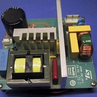
... EVL6563S-ZRC200 demonstration board, a 200 W ripple-free PFC pre- regulator based on an L6563S controller, designed according to the criterion proposed in this application note. Figure 1. EVL6563S-200ZRC 200W PFC demonstration board September 2010 Application note A 200 W ripple-free input current PFC pre-regulator with the L6563S ...
Page 2
Contents Contents 1 Basic topologies with zero-ripple current . . . . . . . . . . . . . . . . . . . . . . . . 4 2 Zero-ripple current phenomenon: theory . . ...
Page 3
... AN3180 List of figures Figure 1. EVL6563S-200ZRC 200W PFC demonstration board . . . . . . . . . . . . . . . . . . . . . . . . . . . . . 1 Figure 2. Some basic topologies with zero-ripple current characteristics . . . . . . . . . . . . . . . . . . . . . . 4 Figure 3. Smoothing transformer and related currents . . . . . . . . . . . . . . . . . . . . . . . . . . . . . . . . . . . . 5 Figure 4. Coupled inductor Figure 5. Coupled inductor Figure 6. Coupled inductor model under zero-ripple current conditions . . . . . . . . . . . . . . . . . . . 8 Figure 7. Ripple-current attenuation as a function of the error sources for various winding coupling 12 Figure 8 ...
Page 4
Basic topologies with zero-ripple current 1 Basic topologies with zero-ripple current Coupled magnetic devices have been around since the early days of electronics, and their application to power switching circuits dates back to the late 70's with the experiments on ...
Page 5
AN3180 All converter topologies are capable of producing zero-ripple current phenomenon, provided there are two or more inductors which have equal (or, more generally, proportional) voltages of equal frequency and phase. Some topologies, such as Cuk and SEPIC, have two ...
Page 6
Zero-ripple current phenomenon: theory 2 Zero-ripple current phenomenon: theory Zero-ripple current in one of a two-winding coupled inductor, having self-inductances L1 and L2, can be achieved if the coupling coefficient k, given by: Equation their mutual inductance), ...
Page 7
AN3180 Figure 5. Coupled inductor Similarly, considering the model of αv(t equally apparent that, in order for the primary ripple current to be zero the voltage across the inductance L the same: Equation 4 If ...
Page 8
Zero-ripple current phenomenon: theory Equation 6 and Equation 5 6 zero-ripple current phenomenon to occur, but unfortunately its physical nature is not shown. To provide some physical insight, let us consider the coupled inductor model (n is ...
Page 9
AN3180 To summarize the main results of this brief analysis: 1. Ripple-current can be reduced to zero in either winding of a two-winding coupled inductor, but not simultaneously 2. The only conditions imposed on the voltages that excite the windings, ...
Page 10
Sensitivity of zero-ripple current condition 3 Sensitivity of zero-ripple current condition In real-world coupled inductors it is unthinkable to reduce the ripple current in a winding to exactly zero and produce a perfect ripple steering. There are two basic reasons ...
Page 11
AN3180 If the attenuation A is defined as the ratio of the residual ripple the ripple that would be there without the coupled inductor (di to the actual ripple on the cancellation winding ...
Page 12
Sensitivity of zero-ripple current condition Figure 7. Ripple-current attenuation as a function of the error sources for various winding coupling 5. A resonance frequency, close to: Equation 12 for small zero-ripple condition mismatches, exists where the gain peaks and attenuation ...
Page 13
AN3180 4 Zero-ripple current phenomenon: practice Before giving details of the practical realization of a coupled inductor able to provide ripple steering useful to draw some conclusions of considerable practical interest from the theoretical analysis carried out in ...
Page 14
Zero-ripple current phenomenon: practice Figure 9. Two-section slotted bobbin suggested for the realization of a coupled inductor - top view result of the aforementioned current splitting action, the same happens to the magnetic flux: the AC winding ...
Page 15
AN3180 At this point, all the elements needed to outline a step-by-step practical design procedure are in place. For the details of steps please refer to the algorithm described in References The case of ...
Page 16
Zero-ripple current phenomenon: practice Equation 17 where, in this case the measured inductance of the AC winding. Add the result, to account for the slight coupling improvement that there is as the DC winding is ...
Page 17
AN3180 bobbin, unless mounting clips or gluing are used (quite impractical to use during the cut- and-try phase). The position of the core inside the bobbin, especially along the direction of the legs, is critical because it changes the position ...
Page 18
Capacitor selection 5 Capacitor selection It is obvious that the capacitance of the smoothing transformer capacitor should be as large as possible and its ESR as low as possible to minimize the impressed voltage mismatch. Although this assertion is always ...
Page 19
... AN3180 6 A 200 W ripple-free input current PFC pre-regulator Figure 13 shows the electrical schematic of the EVL6563S-ZRC200 demonstration board, a 200 W zero-ripple-current PFC pre-regulator (see BOM in topology modified by adding the cancellation winding to the boost inductor and a capacitor, to make a smoothing transformer to minimize the input ripple. ...
Page 20
A 200 W ripple-free input current PFC pre-regulator Figure 13. 200 W PFC pre-regulator with ripple-free input current: electrical schematic 20/39 Doc ID 17273 Rev 1 AN3180 ...
Page 21
... AXIAL stand. m-film res - Doc ID 17273 Rev 1 Supplier SHINDENGEN AVX EPCOS Rubycon Murata NICHICON Murata AVX Murata Murata Murata Murata Murata Murata ARCOTRONICS ARCOTRONICS Murata Murata STMicroelectronics STMicroelectronics VISHAY VISHAY Wickmann STMicroelectronics BC COMPONENTS BC COMPONENTS VISHAY VISHAY VISHAY VISHAY VISHAY VISHAY 21/39 ...
Page 22
... Full-load output voltage ripple Maximum output overvoltage Doc ID 17273 Rev 1 AN3180 Supplier VISHAY VISHAY VISHAY VISHAY VISHAY VISHAY VISHAY VISHAY VISHAY VISHAY VISHAY VISHAY VISHAY VISHAY VISHAY VISHAY EPCOS VISHAY VISHAY STMicroelectronics Value Unit 90 - 265 Vrms 400 Vdc 200 W 40 kHz Vpk-pk 45 Vdc ...
Page 23
AN3180 Table 3. 200 W PFC pre-regulator with ripple-free input current: coupled inductor specification Item Core Bobbin Inductance Windings spec and build Figure 14. Harmonic emissions and conformity to JEITA-MITI standards Figure 15. Harmonic emissions and conformity to EN61000-3-2 standards ...
Page 24
A 200 W ripple-free input current PFC pre-regulator Figure 16. 200W PFC pre-regulator with ripple-free input current: typical performance 24/39 Doc ID 17273 Rev 1 AN3180 ...
Page 25
AN3180 Figure 17. Line current and voltage @ full load (200 W) - Line current and voltage @ 115 Vac -200 W Figure 19. AC and DC winding currents nominal input voltages and full load (200 and ...
Page 26
A 200 W ripple-free input current PFC pre-regulator The zoomed image of mA pk-pk, against a 2.962 A pk-pk of the AC winding current, and so resulting in 0.114/2.962 = 38.5*10-3 (-28.3 dB) attenuation. The EMI filter used for reducing ...
Page 27
AN3180 7 Conclusions The ripple-steering technique, with its ability to reduce an inductor ripple current theoretically to zero, has been discussed and its theoretical base has been outlined. The construction of a coupled inductor is addressed and a practical design ...
Page 28
References 8 References 1. “A 'Zero' Ripple Technique Applicable to Any DC Converter”, Power Electronics Specialists Conference, 1999. PESC 99. 30th Annual IEEE (1999 Volume 2) 2. “The Coupled Inductor Filter: Analysis and Design for AC Systems”, IEEE Transactions on ...
Page 29
AN3180 Electrical equivalent circuit models of coupled inductors and transformers Appendix A Electrical equivalent circuit models of coupled inductors and transformers A system of coupled inductors is a set of coils that share one or more common magnetic paths because ...
Page 30
Electrical equivalent circuit models of coupled inductors and transformers Figure 23. Coupled inductors The mutual inductance M cannot be assigned arbitrarily but must fulfill the inequality: Equation The case L generated by either winding is totally linked ...
Page 31
AN3180 Electrical equivalent circuit models of coupled inductors and transformers Figure 24. Electrical equivalent circuit of coupled inductors The branch-constitutive equations of the circuit are the following: Equation 25 By comparing Equation 25 Equation 26 ⎧ L ⎪ ⎨ M ...
Page 32
Electrical equivalent circuit models of coupled inductors and transformers inductance L is associated to the secondary leakage flux, the flux generated by the b secondary winding and not completely linked to itself nor to the primary winding called ...
Page 33
AN3180 Electrical equivalent circuit models of coupled inductors and transformers Figure 26. Model of coupled inductors with Another interesting and quite frequently used choice This results in a very simple model, illustrated in ...
Page 34
Electrical equivalent circuit models of coupled inductors and transformers Figure 28. Model of coupled inductors with Other possible choices of a are a = M/L related (logically, not physically) to the leakage flux on the secondary ...
Page 35
AN3180 Electrical equivalent circuit models of coupled inductors and transformers is associated to the magnetic flux that flows mostly through the magnetic core and so, is affected by the non-linearity typical of magnetic materials. If the flux density exceeds the ...
Page 36
Measuring transformer and coupled inductor parameters Appendix B Measuring transformer and coupled inductor parameters From a practical point of view there is the need to measure the parameters of coupled inductors (transformers) L circuits. Needless to say that it is ...
Page 37
AN3180 Figure 30. Winding connections: aiding flux (left), opposing flux (right always L > Equation 32 The advantage of this method is its low sensitivity to winding resistance and to the impedance of the wire used ...
Page 38
Revision history Revision history Table 4. Document revision history Date 14-Sep-2010 38/39 Revision 1 Initial release. Doc ID 17273 Rev 1 AN3180 Changes ...
Page 39
... AN3180 Information in this document is provided solely in connection with ST products. STMicroelectronics NV and its subsidiaries (“ST”) reserve the right to make changes, corrections, modifications or improvements, to this document, and the products and services described herein at any time, without notice. All ST products are sold pursuant to ST’s terms and conditions of sale. ...