EVL6563S-100W STMicroelectronics, EVL6563S-100W Datasheet - Page 21
EVL6563S-100W
Manufacturer Part Number
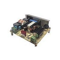
EVL6563S-100W
Description
EVAL BOARD FOR L6563(100W)
Manufacturer
STMicroelectronics
Type
Power Factor Correctionr
Specifications of EVL6563S-100W
Main Purpose
Power Management, Power Factor Correction
Embedded
No
Utilized Ic / Part
L6563
Primary Attributes
100W Power Factor Correction and Preregulator Combination
Secondary Attributes
Transition Mode & Active Tracking Boost Function.
Board Size
90 mm x 83 mm
Maximum Operating Temperature
+ 60 C
Operating Supply Voltage
90 V to 265 V
Product
Power Management Modules
Dimensions
90 mm x 83 mm
Lead Free Status / RoHS Status
Lead free / RoHS Compliant
For Use With/related Products
L6563S
Other names
497-10490


AN3065
For the EVL6563S-100W we have:
●
Once this function is triggered, the gate drive activity is immediately stopped until the
voltage on the pin PFC_OK drops below 2.4 V. An example is given in
Notice that both feedback dividers connected to L6563S V_INV (pin #1) and PFC_OK (pin
#7) can be selected without any constraints. The unique criterion is that both dividers have
to sink a current from the output bus which needs to be significantly higher than the current
biasing the error amplifier and PFC_OK comparator.
The OVP function described above is able to handle "normal" overvoltage conditions, i.e.
those resulting from an abrupt load/line change or occurring at startup. In case the
overvoltage is generated by a feedback disconnection, for instance, when one of the upper
resistors of the output divider fails open, an additional circuitry detects the voltage drop of
pin INV. If the voltage on pin INV is lower than 1.66 V and at the same time OVP is active, a
feedback failure is assumed. Thus, the gate drive activity is immediately stopped, the device
is shut down, its quiescent consumption is reduced below 180 µA and the condition is
latched as long as the supply voltage of the IC is above the UVLO threshold. To restart the
system, it is necessary to recycle the input power, so that the Vcc voltage of the L6563S
goes below 6 V and that one of the PWM controllers goes below its UVLO threshold.
Note that this function offers a complete protection against not only feedback loop failures or
erroneous settings, but also against a failure of the protection itself. Either resistor of the
PFC_OK divider failing short or open or a PFC_OK pin floating results in shutting down the
IC and stopping the pre-regulator.
Moreover, the pin PFC_OK doubles its function as a non-latched IC disable. A voltage
below 0.23V shuts down the IC, reducing its consumption below 2 mA. To restart the IC,
simply let the voltage at the pin go above 0.27 V.
For the EVL6563H-100W we have:
–
–
–
–
then:
V
V
Select: R3+R4+R11 = 8.8 MΩ
R15 = 8.8 MΩ ·2.5/(434-2.5) = 51 kΩ
O
OVP
= 400 V
= 434 V
Doc ID 16279 Rev 2
Test results and significant waveforms
Figure
29.
21/33
Related parts for EVL6563S-100W
Image
Part Number
Description
Manufacturer
Datasheet
Request
R

Part Number:
Description:
EVAL BOARD FOR L6563(250W)
Manufacturer:
STMicroelectronics
Datasheet:

Part Number:
Description:
EVAL BOARD FOR L6563(400W)
Manufacturer:
STMicroelectronics
Datasheet:

Part Number:
Description:
Power Management Modules & Development Tools Tranisition Mode PFC L6563S EVL Board
Manufacturer:
STMicroelectronics
Datasheet:

Part Number:
Description:
EVAL BOARD L6563 (200W)
Manufacturer:
STMicroelectronics
Datasheet:
Part Number:
Description:
STMicroelectronics [RIPPLE-CARRY BINARY COUNTER/DIVIDERS]
Manufacturer:
STMicroelectronics
Datasheet:
Part Number:
Description:
STMicroelectronics [LIQUID-CRYSTAL DISPLAY DRIVERS]
Manufacturer:
STMicroelectronics
Datasheet:

Part Number:
Description:
BOARD EVAL FOR MEMS SENSORS
Manufacturer:
STMicroelectronics
Datasheet:
Part Number:
Description:
NPN TRANSISTOR POWER MODULE
Manufacturer:
STMicroelectronics
Datasheet:
Part Number:
Description:
TURBOSWITCH ULTRA-FAST HIGH VOLTAGE DIODE
Manufacturer:
STMicroelectronics
Datasheet:
Part Number:
Description:
Manufacturer:
STMicroelectronics
Datasheet:
Part Number:
Description:
DIODE / SCR MODULE
Manufacturer:
STMicroelectronics
Datasheet:
Part Number:
Description:
DIODE / SCR MODULE
Manufacturer:
STMicroelectronics
Datasheet: