EVL6563S-100W STMicroelectronics, EVL6563S-100W Datasheet - Page 20
EVL6563S-100W
Manufacturer Part Number
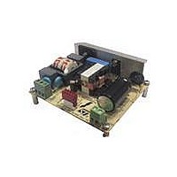
EVL6563S-100W
Description
EVAL BOARD FOR L6563(100W)
Manufacturer
STMicroelectronics
Type
Power Factor Correctionr
Specifications of EVL6563S-100W
Main Purpose
Power Management, Power Factor Correction
Embedded
No
Utilized Ic / Part
L6563
Primary Attributes
100W Power Factor Correction and Preregulator Combination
Secondary Attributes
Transition Mode & Active Tracking Boost Function.
Board Size
90 mm x 83 mm
Maximum Operating Temperature
+ 60 C
Operating Supply Voltage
90 V to 265 V
Product
Power Management Modules
Dimensions
90 mm x 83 mm
Lead Free Status / RoHS Status
Lead free / RoHS Compliant
For Use With/related Products
L6563S
Other names
497-10490


Test results and significant waveforms
4.4
4.5
20/33
Figure 27. EVL6563S-100W TM PFC startup at
CH1: PFC output voltage
CH2: Vcc voltage (pin #14)
CH3: RUN (pin #10)
CH4: Gate drive (pin #13)
Startup operation
On this demonstration board the startup resistors R7 and R16 charge C10 and C11 until the
L6563S turn-on voltage threshold is reached, at which point the L6563S starts switching.
Because once the turn-on threshold is reached the Vcc consumption increases and the
current supplied by R7 and R16 is lower, the L6563S is initially supplied by the Vcc
capacitor, and then the L1 auxiliary winding provides the voltage to supply the IC.
In the following
plug-in are shown. We can notice that the Vcc voltage rises up to the turn-on threshold, and
the L6563S starts operating. As mentioned previously, for a short time the energy is
supplied by the Vcc capacitor, and then the auxiliary winding with the charge pump circuit
takes over. At the same time, the output voltage rises from the peak value of the rectified
mains to the nominal value of the PFC output voltage. The good margin of the
compensation network allows a clean startup, without any large overshoot.
PFC_OK pin and feedback failure (open loop) protection
During normal operation, the voltage control loop provides for the output voltage (Vout) of
the PFC pre-regulator close to its nominal value, set by the resistor ratio of the feedback
output divider. In the L6563S the PFC_OK pin has been dedicated to monitor the output
voltage with a separate resistor divider composed of R3, R6, R11 (high) and R15 (low), see
Figure
voltage exceeds a preset value (V
expected, also including worst-case load/line transients.
90 Vac, 60 Hz, full load
2. This divider is selected so that the voltage at the pin reaches 2.5 V if the output
Figure 27
and
Doc ID 16279 Rev 2
28
the waveforms during the startup of the circuit at mains
OVP
), usually larger than the maximum Vout that can be
Figure 28. EVL6563S-100W TM PFC startup at
CH1: PFC output voltage
CH2: Vcc voltage (pin #14)
CH3: RUN (pin #10)
CH4: Gate drive (pin #13)
265 Vac, 50 Hz, full load
AN3065
Related parts for EVL6563S-100W
Image
Part Number
Description
Manufacturer
Datasheet
Request
R

Part Number:
Description:
EVAL BOARD FOR L6563(250W)
Manufacturer:
STMicroelectronics
Datasheet:

Part Number:
Description:
EVAL BOARD FOR L6563(400W)
Manufacturer:
STMicroelectronics
Datasheet:

Part Number:
Description:
Power Management Modules & Development Tools Tranisition Mode PFC L6563S EVL Board
Manufacturer:
STMicroelectronics
Datasheet:

Part Number:
Description:
EVAL BOARD L6563 (200W)
Manufacturer:
STMicroelectronics
Datasheet:
Part Number:
Description:
STMicroelectronics [RIPPLE-CARRY BINARY COUNTER/DIVIDERS]
Manufacturer:
STMicroelectronics
Datasheet:
Part Number:
Description:
STMicroelectronics [LIQUID-CRYSTAL DISPLAY DRIVERS]
Manufacturer:
STMicroelectronics
Datasheet:

Part Number:
Description:
BOARD EVAL FOR MEMS SENSORS
Manufacturer:
STMicroelectronics
Datasheet:
Part Number:
Description:
NPN TRANSISTOR POWER MODULE
Manufacturer:
STMicroelectronics
Datasheet:
Part Number:
Description:
TURBOSWITCH ULTRA-FAST HIGH VOLTAGE DIODE
Manufacturer:
STMicroelectronics
Datasheet:
Part Number:
Description:
Manufacturer:
STMicroelectronics
Datasheet:
Part Number:
Description:
DIODE / SCR MODULE
Manufacturer:
STMicroelectronics
Datasheet:
Part Number:
Description:
DIODE / SCR MODULE
Manufacturer:
STMicroelectronics
Datasheet: