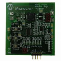
MCP1631RD-MCC2 Microchip Technology, MCP1631RD-MCC2 Datasheet - Page 9

MCP1631RD-MCC2
Manufacturer Part Number
MCP1631RD-MCC2
Description
REFERENCE DESIGN MCP1631HV
Manufacturer
Microchip Technology
Datasheets
1.MCP1631VHVT-330EST.pdf
(34 pages)
2.MCP1631HV-330EST.pdf
(54 pages)
3.MCP1631RD-MCC2.pdf
(20 pages)
4.MCP1631RD-MCC2.pdf
(328 pages)
Specifications of MCP1631RD-MCC2
Main Purpose
Power Management, Battery Charger
Embedded
Yes, MCU, 8-Bit
Utilized Ic / Part
MCP1631HV, PIC16F883
Primary Attributes
1 ~ 2 Cell- Li-Ion, 1 ~ 5 Cell- NiCd/NiMH, 1 ~ 2 1W LEDs
Secondary Attributes
Status LEDs
Silicon Manufacturer
Microchip
Application Sub Type
Battery Charger
Kit Application Type
Power Management - Battery
Silicon Core Number
MCP1631HV, PIC16F883
Kit Contents
Board
Lead Free Status / RoHS Status
Lead free / RoHS Compliant
Lead Free Status / RoHS Status
Lead free / RoHS Compliant
System Level Block Diagram
The system level block diagram shown in
represents all of the MCP1631HV internal blocks. The
SHDN input is used to turn off the charger and lower
FIGURE 8:
© 2007 Microchip Technology Inc.
SHDN
A
OSC
OV
CS/VR
V
COMP
V
FB
VDD_OUT
IN
REF
IN
Note 1: For Shutdown control, amplifier A3 remains functional so
IN
AMP
/ A
A
V
-
GND
+
A1
VDD_IN
battery voltage can be sensed during discharge phase.
DD
+3.3V or +5.0V
LDO
250 mA
MCP1631HV Block Diagram.
2.7V Clamp
V
DD
2R
V
Shutdown Control
A3 Remains On
DD
MCP1631HV/VHV High-Speed Analog PWM
0.1 µA
+
C1
-
V
V
DD
DD
OSC
Figure 7
R
R
S
DIS
Internal
1.2V V
100 kΩ
REF
the quiescent current draw to a 4.4 µA typical, the +5V
generated bias is available and A3 remain powered for
battery monitoring and microcontroller power.
UVLO
+
V
-
C2
DD
Q
Overvoltage Comp
w/ Hysteresis
Q
OT
10R
V
V
A3
A2
DD
DD
P
VDD
+
+
-
-
AN1137
R
R
DS01137A-page 9
P
V
GND
100 kΩ
VS
EXT
IS
VS
OUT
OUT
IS
IN
IN


