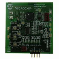
MCP1631RD-MCC2 Microchip Technology, MCP1631RD-MCC2 Datasheet - Page 3

MCP1631RD-MCC2
Manufacturer Part Number
MCP1631RD-MCC2
Description
REFERENCE DESIGN MCP1631HV
Manufacturer
Microchip Technology
Datasheets
1.MCP1631VHVT-330EST.pdf
(34 pages)
2.MCP1631HV-330EST.pdf
(54 pages)
3.MCP1631RD-MCC2.pdf
(20 pages)
4.MCP1631RD-MCC2.pdf
(328 pages)
Specifications of MCP1631RD-MCC2
Main Purpose
Power Management, Battery Charger
Embedded
Yes, MCU, 8-Bit
Utilized Ic / Part
MCP1631HV, PIC16F883
Primary Attributes
1 ~ 2 Cell- Li-Ion, 1 ~ 5 Cell- NiCd/NiMH, 1 ~ 2 1W LEDs
Secondary Attributes
Status LEDs
Silicon Manufacturer
Microchip
Application Sub Type
Battery Charger
Kit Application Type
Power Management - Battery
Silicon Core Number
MCP1631HV, PIC16F883
Kit Contents
Board
Lead Free Status / RoHS Status
Lead free / RoHS Compliant
Lead Free Status / RoHS Status
Lead free / RoHS Compliant
FIGURE 2:
Multi-Chemistry Charger
There are significant differences in the charge profile
between Ni batteries versus Li-Ion batteries. A multi-
chemistry charger must be able to implement the
proper profile and proper termination methods. This
application note will demonstrate a charger that has the
capability to charge single or multiple cells in series.
THE POWER BEHIND CHARGING
BATTERIES
A battery charger and power supply have a lot in
common, delivering a regulated output from a varying
input. Two solutions are prevalent, linear and switch
mode solutions. The linear solution is commonly used
for low input voltage or low power applications. Its main
drawback is internal power dissipation, calculated by
the following formula:
For example, a +12V input linear charger would
dissipate 18 watts when charging a +3.0V Li-Ion battery
at 2A. Any power dissipation over a few watts is a
challenge to cool.
Cooling 18 watts of power dissipation is no easy task,
airflow and large heatsinks are required making a linear
solution impractical.
© 2007 Microchip Technology Inc.
P
V
DISS
ICH (A)
CELL
T(°C)
(V)
=
(
V
IN
Stage 1
Pre-Charge
I
CH
Li-Ion Charge Profile.
–
= 0.2C
V
2.8V
BATT
) I
×
CHARGE
Stage 2
Constant Current
Pack T (°C)
Li-Ion Charge Profile
I
CH
= 1.0C
V
CELL
A switching charger solution operating at similar
conditions
approximately 1.05 Watts, making it much easier to
cool. For high input voltage applications, switching
battery chargers are smaller and more cost effective.
Stage 3
Constant Voltage
P
DISS
at
4.2V
85%
=
P
OUT
I
CH
efficiency
= 0.07C
×
⎛
⎝
1 Eff
--------------- -
Stage 4
Termination
I
CH
AN1137
–
Eff
would
= 0C
DS01137A-page 3
·
⎞
⎠
dissipate


