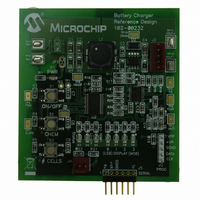
MCP1631RD-MCC2 Microchip Technology, MCP1631RD-MCC2 Datasheet - Page 5

MCP1631RD-MCC2
Manufacturer Part Number
MCP1631RD-MCC2
Description
REFERENCE DESIGN MCP1631HV
Manufacturer
Microchip Technology
Datasheets
1.MCP1631VHVT-330EST.pdf
(34 pages)
2.MCP1631HV-330EST.pdf
(54 pages)
3.MCP1631RD-MCC2.pdf
(20 pages)
4.MCP1631RD-MCC2.pdf
(328 pages)
Specifications of MCP1631RD-MCC2
Main Purpose
Power Management, Battery Charger
Embedded
Yes, MCU, 8-Bit
Utilized Ic / Part
MCP1631HV, PIC16F883
Primary Attributes
1 ~ 2 Cell- Li-Ion, 1 ~ 5 Cell- NiCd/NiMH, 1 ~ 2 1W LEDs
Secondary Attributes
Status LEDs
Silicon Manufacturer
Microchip
Application Sub Type
Battery Charger
Kit Application Type
Power Management - Battery
Silicon Core Number
MCP1631HV, PIC16F883
Kit Contents
Board
Lead Free Status / RoHS Status
Lead free / RoHS Compliant
Lead Free Status / RoHS Status
Lead free / RoHS Compliant
analog to digital converter(A/D), computes the desired
charge current and adjusts the SEPIC controlled
current source up or down.
To develop the charge algorithm for the NiMH battery,
the microcontroller A/D converter is used to measure
the battery pack voltage, when the pack voltage is
within the desired range, the microcontroller sets the
proper current level. To terminate the charge, two A/D
inputs are used, one to sense the decreasing battery
voltage and one to sense the increasing battery pack
temperature. Charge termination will occur, if either
one or both are detected.
To develop the algorithm for charging Li-Ion batteries,
the A/D converter is used to measure pack voltage.
Depending on pack voltage, the microcontroller will set
the appropriate charge current. Once the pack voltage
reaches the constant voltage phase, the A/D converter
senses and regulates the pack voltage by adjusting the
amount of current into the battery. The current contin-
ues to decrease until is reaches about 7% of the fast
charge value. At this point, the microcontroller
terminates the charge.
The MCP1631HV Implementation
The MCP1631HV integrates the necessary blocks to
develop an intelligent, programmable battery charger
or constant current source used for driving high power
LED’s.
INPUT VOLTAGE AND BIAS GENERATION
The MCP1631HV provides a regulated bias voltage for
internal circuitry that is available for biasing the micro-
controller and other components. It is available in two
regulated voltage options, +5.0V and +3.3V and can
handle a maximum output current of 250 mA. The
maximum input voltage range for the regulator is
+16.0V and can withstand transients to +18.0V. For
regulated input voltages or higher input voltage
applications, the MCP1631 device option without
internal regulator can be used. By using a high voltage
regulator to bias the MCP1631 and microcontroller, the
range of input voltage for the design is only limited by
the regulator maximum input and power train design.
© 2007 Microchip Technology Inc.
FIGURE 4:
Bias Voltage Options.
V
High Voltage
Input
IN
V
IN
= +5.3V to +16.0V
A
= +3.8V to +16.0V
C
VDD_IN
C
C
C
Regulator
µController
MCP1631HV
V
Voltage
Linear
= USB +5.0V
MCP1631HV
DD
High
Input
+3.3V or +5.0V
MCP1631HV and MCP1631
Regulated
C
µController
MCP1631
A
VDD_OUT
A
VDD_OUT
C
C
AN1137
250 mA Available
= +5.0V
250 mA Available
DS01137A-page 5
= +3.3V
MCP1631
V
µController
V
DD
µController
DD
Input
Input


