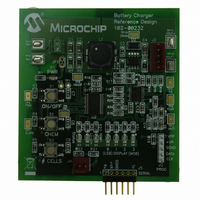
MCP1631RD-MCC2 Microchip Technology, MCP1631RD-MCC2 Datasheet - Page 18

MCP1631RD-MCC2
Manufacturer Part Number
MCP1631RD-MCC2
Description
REFERENCE DESIGN MCP1631HV
Manufacturer
Microchip Technology
Datasheets
1.MCP1631VHVT-330EST.pdf
(34 pages)
2.MCP1631HV-330EST.pdf
(54 pages)
3.MCP1631RD-MCC2.pdf
(20 pages)
4.MCP1631RD-MCC2.pdf
(328 pages)
Specifications of MCP1631RD-MCC2
Main Purpose
Power Management, Battery Charger
Embedded
Yes, MCU, 8-Bit
Utilized Ic / Part
MCP1631HV, PIC16F883
Primary Attributes
1 ~ 2 Cell- Li-Ion, 1 ~ 5 Cell- NiCd/NiMH, 1 ~ 2 1W LEDs
Secondary Attributes
Status LEDs
Silicon Manufacturer
Microchip
Application Sub Type
Battery Charger
Kit Application Type
Power Management - Battery
Silicon Core Number
MCP1631HV, PIC16F883
Kit Contents
Board
Lead Free Status / RoHS Status
Lead free / RoHS Compliant
Lead Free Status / RoHS Status
Lead free / RoHS Compliant
AN1137
As an approximation, the RMS current in C
For worst-case situations, the RMS current in the C
coupling capacitor is equal to 2A x (4.2V / 12V)
1.18A. The current rating for small multi-layer ceramic
capacitors is typically much higher than 1.18A. For
higher power applications, it may be necessary to use
multiple capacitors in parallel to keep the RMS current
within ratings.
DS01137A-page 18
I
C1 RMS
(
)
=
I
OUT
×
V
OUT
⁄
V
IN
1
:
1/2
or
1
CONCLUSION
For applications that require intelligent power manage-
ment solutions like battery chargers, the combination of
a microcontroller and MCP1631 high-speed PWM is
very powerful. It brings the programmability benefits of
the microcontroller and adds the performance of a
high-speed analog PWM. The analog PWM will
respond to changes in input voltage and output current
very quickly. No code or execution time is necessary to
regulate or protect the circuit. The microcontroller is
used for programmability, establishing charge profile
conditions and monitoring the circuit for fault conditions
and taking the appropriate action, in the event of a
specific fault.
© 2007 Microchip Technology Inc.


