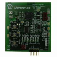
MCP1631RD-MCC2 Microchip Technology, MCP1631RD-MCC2 Datasheet - Page 16

MCP1631RD-MCC2
Manufacturer Part Number
MCP1631RD-MCC2
Description
REFERENCE DESIGN MCP1631HV
Manufacturer
Microchip Technology
Datasheets
1.MCP1631VHVT-330EST.pdf
(34 pages)
2.MCP1631HV-330EST.pdf
(54 pages)
3.MCP1631RD-MCC2.pdf
(20 pages)
4.MCP1631RD-MCC2.pdf
(328 pages)
Specifications of MCP1631RD-MCC2
Main Purpose
Power Management, Battery Charger
Embedded
Yes, MCU, 8-Bit
Utilized Ic / Part
MCP1631HV, PIC16F883
Primary Attributes
1 ~ 2 Cell- Li-Ion, 1 ~ 5 Cell- NiCd/NiMH, 1 ~ 2 1W LEDs
Secondary Attributes
Status LEDs
Silicon Manufacturer
Microchip
Application Sub Type
Battery Charger
Kit Application Type
Power Management - Battery
Silicon Core Number
MCP1631HV, PIC16F883
Kit Contents
Board
Lead Free Status / RoHS Status
Lead free / RoHS Compliant
Lead Free Status / RoHS Status
Lead free / RoHS Compliant
AN1137
Inductor Winding Current Calculation
The first step to calculating the inductor winding current
is to know the maximum output power. For this
constant current battery charger application, the output
power is simply the maximum output voltage times the
charge current.
Maximum output voltage is equal to 4.2V (1 battery @
4.2V).
Since energy is conserved, the input power is equal to
the output power (assuming 100% efficiency). An
efficiency estimate can be used to closer approximate
the input current.
The average input current is equal to the input power
divided by the input voltage:
The
calculation was shown earlier. Given the derived
transfer function and the maximum voltage on the
output of the converter to be 4.2V, the switch on time is
estimated.
Switch On Time:
For the 12V input and 4.2V output case, the switch ON
time is estimated to be approximately 519 ns. (500 kHz
switching frequency).
DS01137A-page 16
Where:
Where:
I
I
INAVG
INAVG
P
OUT
P
P
peak-to-peak
IN
IN
=4.2V x 2 A or 8.4 Watts.
t
ON
P
=
=
=
=
P
OUT
IN
=
I
IN AVG )
=
V
--------------------------------------------------- -
=
(
8.4 Watts / 85%; 85% used as a
typical efficiency estimate
9.88 Watts
9.88 Watts/12V (Nominal)
824 mA. (Typical average input
current
OUT
P
V
OUT
W
OUT
1
⁄
)
(
=
⁄
V
F
×
(
OUT
inductor
SW
Efficiency
P
I
CHARGE
IN
+
⁄
V
V
IN
IN
)
current
)
ripple
The input peak-to-peak ripple current can be
calculated:.
The ripple current in winding (W
similar fashion. The main difference is that the average
current in W
The coupled inductor winding currents calculated
above are used to determine the size of the inductor
necessary. High switching frequency has several
advantages, smaller ripple current, lower peak and
RMS current and lower volt-time product on the
inductor core. This leads to a small, low-cost solution.
SEPIC Switch Current and Voltage Calculations
The switch current (I
the winding currents during the switch on time. When
the switch is turned on, it conducts the current in W
and W
The minimum switch current is equal to:
RMS of a Trapezoidal waveform
The RMS value of the switch current is approximately
1.44 mA.
GIVEN:
Input Peak-to-Peak Ripple Current (W
W
Where:
I
I
Note:
L(W2)MIN
L(W2)MIN
2
I
I
L(W2)PK
L(W2)PK
ΔI
Peak-to-Peak Ripple Current
I
I
I
I
I
SW
SWPK
SWMIN
L(W1)MIN
L(W1)MIN
I
I
L(W2)
L(W1)PK
L(W1)PK
2
ΔI
.
I
I
A
B
= I
L(W1)
I
= 2.82A + 311 mA = 3.14A
W1
SWRMS
In the case of V
W
= 2.82A - 311 mA = 2.51A
2
= (12V / 20 µH) x t
= I
= 2.16 A for winding 2 (W
= I
= 1.85 A for winding 1 (W
is equal to I
1
=
=
+ I
L
= W
OUTAVG
OUTAVG
W1
=
=
=
=
=
W2
=
2
= L
2.51A = Minimum,
3.14A = Maximum
= 2.82A (Average)
Q1
(12V / 20 µH) x t
I
980 mA for winding 1 (W
I
669 mA for winding 1 (W
(ripple and average).
INAVG
INAVG
D
W2
) is equal to the combination of
© 2007 Microchip Technology Inc.
+1/2 x ΔI
-1/2 x ΔI
×
OUT
= 20 µH (10 µH Coupled)
⎛
⎜
⎝
IN
+1/2 x ΔI
-1/2 x ΔI
I
-------------------------------------- -
2
A
or 2A in this application.
= V
+
ON
I
L(W2)
A
L(W2)
OUT
2
×
3
) is calculated in a
= 311 mA
L(W1)
I
L(W1)
, the current in
B
ON
1
+
2
2
)
)
)
I
= 311 mA
2
B
⎞
⎟
⎠
1
1
)
)
1


