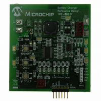
MCP1631RD-MCC2 Microchip Technology, MCP1631RD-MCC2 Datasheet - Page 4

MCP1631RD-MCC2
Manufacturer Part Number
MCP1631RD-MCC2
Description
REFERENCE DESIGN MCP1631HV
Manufacturer
Microchip Technology
Datasheets
1.MCP1631VHVT-330EST.pdf
(34 pages)
2.MCP1631HV-330EST.pdf
(54 pages)
3.MCP1631RD-MCC2.pdf
(20 pages)
4.MCP1631RD-MCC2.pdf
(328 pages)
Specifications of MCP1631RD-MCC2
Main Purpose
Power Management, Battery Charger
Embedded
Yes, MCU, 8-Bit
Utilized Ic / Part
MCP1631HV, PIC16F883
Primary Attributes
1 ~ 2 Cell- Li-Ion, 1 ~ 5 Cell- NiCd/NiMH, 1 ~ 2 1W LEDs
Secondary Attributes
Status LEDs
Silicon Manufacturer
Microchip
Application Sub Type
Battery Charger
Kit Application Type
Power Management - Battery
Silicon Core Number
MCP1631HV, PIC16F883
Kit Contents
Board
Lead Free Status / RoHS Status
Lead free / RoHS Compliant
Lead Free Status / RoHS Status
Lead free / RoHS Compliant
AN1137
CHARGER POWER TOPOLOGY
Many switching regulator power topologies exist, buck,
boost, SEPIC and flyback are all used to develop
switching battery chargers (including others for very
high power applications). A SEPIC converter is
commonly used, it has advantages over buck and
boost converters when used in battery charger
applications.
• Capacitive Isolation:
FIGURE 3:
MULTI-CHEMISTRY BATTERY
CHARGER DESIGN
The development of an intelligent multi-chemistry
battery charger starts with the microcontroller. By
implementing the charge algorithm in code, the charger
can be adapted for multi-chemistry, custom charge
profile and unique applications. For dc-dc converters,
switching at high frequency with high performance gate
drive capability, PWM control and high-speed protec-
tion, specialized analog circuitry is required. A new
high-speed analog PWM, the MCP1631HV was
developed for constant current SEPIC applications
(battery chargers and LED drivers). By implementing
the pulse width modulation, PWM, control using the
DS01137A-page 4
- There is no direct dc path from input to output
providing isolation, this results in less power
components and a safer battery charger.
Input Current
SEPIC Topology.
+12V Input
Coupled Inductor
C
IN
Switch
V
SEPIC Converter
CS
EXT
R
LIMIT
1
• Primary Inductive Converter:
• Single Low Side Switch:
• Buck-Boost Capability:
MCP1631, the battery charger has the benefits of
analog speed and resolution. By controlling the charge
algorithm using the microcontroller, the battery charger
has the intelligence and flexibility to generate a profile
for all battery types using digital timers and
programmed algorithms.
As complex as this project sounds, it is really quite
simple if the SEPIC converter is thought of as a micro-
controller controlled current source. To increase cur-
rent, the microcontroller simply increases the V
input to the MCP1631HV and to decrease current, the
microcontroller decreases the V
MCP1631HV. To generate a charge algorithm, the
microcontroller measures the battery voltage using an
Capacitive Isolation
C
- The SEPIC converter topology has an induc-
- A single low side switch reduces MOSFET
- For applications where the input voltage can
C
tor at the input, smoothing input current
reducing necessary filtering and generated
source noise.
drive and current limit protection complexity.
be above or below the battery voltage a
SEPIC can buck or boost the input voltage.
1
I
SENSE
© 2007 Microchip Technology Inc.
Blocking Diode
C
Batteries
OUT
+Vbatt
REF
input to the
REF


