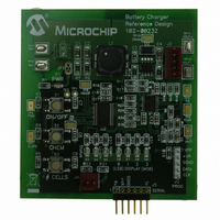
MCP1631RD-MCC2 Microchip Technology, MCP1631RD-MCC2 Datasheet - Page 7

MCP1631RD-MCC2
Manufacturer Part Number
MCP1631RD-MCC2
Description
REFERENCE DESIGN MCP1631HV
Manufacturer
Microchip Technology
Datasheets
1.MCP1631VHVT-330EST.pdf
(34 pages)
2.MCP1631HV-330EST.pdf
(54 pages)
3.MCP1631RD-MCC2.pdf
(20 pages)
4.MCP1631RD-MCC2.pdf
(328 pages)
Specifications of MCP1631RD-MCC2
Main Purpose
Power Management, Battery Charger
Embedded
Yes, MCU, 8-Bit
Utilized Ic / Part
MCP1631HV, PIC16F883
Primary Attributes
1 ~ 2 Cell- Li-Ion, 1 ~ 5 Cell- NiCd/NiMH, 1 ~ 2 1W LEDs
Secondary Attributes
Status LEDs
Silicon Manufacturer
Microchip
Application Sub Type
Battery Charger
Kit Application Type
Power Management - Battery
Silicon Core Number
MCP1631HV, PIC16F883
Kit Contents
Board
Lead Free Status / RoHS Status
Lead free / RoHS Compliant
Lead Free Status / RoHS Status
Lead free / RoHS Compliant
CURRENT REGULATION
To sense battery current for regulation in a SEPIC con-
verter, the secondary winding of the coupled inductor
can be used. The average current flowing through the
secondary winding is equal to the current flowing into
the battery. As shown, this topology does not require
the sense resistor in series with the battery, removing
any power lost in series with the battery while running
the system. When sensing battery current, a low value
sense resistor is desired to minimize power loss, the
FIGURE 6:
SENSING BATTERY VOLTAGE
Using the internal microcontroller A/D converter to
sense battery voltage is a popular approach. An issue
with this technique is the A/D converter requires a low
source impedance to perform accurate readings. Low
source impedance requires low resistance values that
draw excessive quiescent current from the battery. The
MCP1631HV integrates a low current amplifier (A3),
configured as a unity gain buffer. The buffer output
impedance is low, driving the SAR A/D converter, while
consuming very little quiescent current. A high value
resistor divider is used to drop the battery voltage to an
acceptable range. R1, R2 and R3 values are selected
to minimize the drain on the batteries, typically drawing
on the order of 1 µA. The microcontroller reads the A/D
converter, calculates the current setting and adjusts the
V
Overvoltage (OV) protection is a common battery
charger protection feature. The OV protection is not
there to protect the battery, it is used to protect the
power train from excessive voltage if the battery is
© 2007 Microchip Technology Inc.
REF
input to regulate current.
V
V
REF
FB
+
-
CS INPUT
Current Regulation Diagram.
A1
10X I
BATT
2R
R
+
-
C1
V
C
IN
IN
10R
A2
+
-
MCP1631HV integrates an inverting 10V/V gain
amplifier to increase the battery current sense signal.
The microcontroller sets the V
current level, the MCP1631HV uses the V
a reference for regulation.
The resistor in series with the external SEPIC switch
provides a high speed current limit protecting the
switch and other power train components from a short
circuit or over current condition.
removed or opens. OV protection is typically required
for any current source application (battery chargers,
LED drivers).
The MCP1631HV integrates an internal high speed OV
comparator that has a 1.2V reference connected to its
inverting input. If the voltage on the OV_IN pin exceeds
the 1.2V threshold, the V
terminated. Switching will resume after the voltage has
dropped more than the built in 50 mV of hysteresis. If a
battery is removed during the charge cycle, the charger
output voltage will be limited to a safe value.
I
BATT
R
R
I
INPUT
EXT
output is asychronously
REF
AN1137
input to the desired
BATT
C
DS01137A-page 7
OUT
REF
input as


