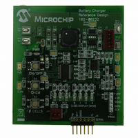
MCP1631RD-MCC2 Microchip Technology, MCP1631RD-MCC2 Datasheet - Page 13

MCP1631RD-MCC2
Manufacturer Part Number
MCP1631RD-MCC2
Description
REFERENCE DESIGN MCP1631HV
Manufacturer
Microchip Technology
Datasheets
1.MCP1631VHVT-330EST.pdf
(34 pages)
2.MCP1631HV-330EST.pdf
(54 pages)
3.MCP1631RD-MCC2.pdf
(20 pages)
4.MCP1631RD-MCC2.pdf
(328 pages)
Specifications of MCP1631RD-MCC2
Main Purpose
Power Management, Battery Charger
Embedded
Yes, MCU, 8-Bit
Utilized Ic / Part
MCP1631HV, PIC16F883
Primary Attributes
1 ~ 2 Cell- Li-Ion, 1 ~ 5 Cell- NiCd/NiMH, 1 ~ 2 1W LEDs
Secondary Attributes
Status LEDs
Silicon Manufacturer
Microchip
Application Sub Type
Battery Charger
Kit Application Type
Power Management - Battery
Silicon Core Number
MCP1631HV, PIC16F883
Kit Contents
Board
Lead Free Status / RoHS Status
Lead free / RoHS Compliant
Lead Free Status / RoHS Status
Lead free / RoHS Compliant
THE DESIGN DETAILS OF CHARGING
BATTERIES USING THE PIC
MICROCONTROLLER AND
MCP1631HV WITH A SEPIC
TOPOLOGY
Design Example:
• V
• V
• I
• I
• I
• Overvoltage Protection
SEPIC Power Train Design
• Calculate Maximum Output Power
P
• By making an efficiency estimate, the converter
• P
• I
With I
for each winding is known.
Inductor Ripple Current
For the coupled inductor, the effective inductance is
twice the value of the inductor, this is a result of 2x the
voltage across 2x the number of turns. Since the value
of L is proportional to n
twice the actual value of the inductor.
© 2007 Microchip Technology Inc.
OUT
input power can be estimated. The typical
efficiency of a SEPIC converter in this power
range using a schottky diode for the output
rectifier is around 85%.
- I
- I
BATT
BATT
BATT
IN
IN
BATT
IN
IN
IN
= P
IN
= 4.2V X 2.0A or 8.4 Watts
= 12V
= 8.4 Watts / 0.85 or 9.88 Watts
= +12V / 0.88 Watts
= 1.21 A
= 200 mA Pre-Charge Current
= 2A Fast Charge Current
= 140 mA termination or “tail” current
and I
IN
= 0V to 4.2V
P
/ I
OUT
IN
BATT
P
IN
known, the average inductor current
=
=
2 V
------------
V
-------------------------- -
Efficiency
n
BATT
×
2
, the effective inductance is
2
P
OUT
×
I
BATT
®
A 10 µH inductor looks like a 20 µH inductor (for
coupled inductors only). Larger inductance reduces
ripple current and operates in the continuous mode at
lighter loads, an advantage over non-coupled inductor
solutions.
The input and output inductor ripple current is equal to:
Where T
turned on:
Where Duty Cycle for a SEPIC converter operating in
continuous conduction mode is equal to:
To derive the transfer function of the SEPIC converter,
start by balancing the inductor volt-time product in the
boost stage (W
Q
Q
Inductor slope’s must be equal for volt-time balance:
Multiply both sides by 1/(t
Solve for V
For the second stage, the inductor slopes must also be
equal.
Q
1
1
1
Turned on (+ Slope):
Turned off (- Slope):
Turned on (+ Slope):
V
t
IN
ON
ON
DutyCycle
t
ΔI
×
ON
×
C1
V
D
is the amount of time the SEPIC switch is
W1
--------- -
L
V
C1
: .
W1
ΔI
IN
=
1
⁄
=
ΔI
).
t
=
W1
OFF
(
=
V
DutyCycle
L
V
C1
ΔI
------------
⁄
t
t
IN
ON
t
OFF
=
ON
=
W2
+
×
V
V
--------------------------------------------
=
⎛
⎝
V
----- -
×
=
OUT
=
L
ON
C1
------------ -
1 D
L
V
--------------------------------------------
–
1
--------------------------- -
V
V
--------- -
L
V
+
C1
×
+ t
IN
W2
C1
OUT
–
V
L
⎞
⎠
t
+
OFF
V
V
⁄
OUT
W1
ON
–
L
V
IN
×
OUT
L
W1
V
AN1137
OUT
W1
):
)
+
OUT
–
--------- -
F
×
DS01137A-page 13
V
V
1
SW
(
–
1 D
IN
IN
V
–
IN
)


