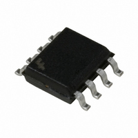
FAN6520AIMX Fairchild Semiconductor, FAN6520AIMX Datasheet - Page 2

FAN6520AIMX
Manufacturer Part Number
FAN6520AIMX
Description
IC CTRLR PWM SGL SYNC BUCK 8SOIC
Manufacturer
Fairchild Semiconductor
Type
Step-Down (Buck)r
Datasheet
1.FAN6520AMX.pdf
(15 pages)
Specifications of FAN6520AIMX
Internal Switch(s)
No
Synchronous Rectifier
Yes
Number Of Outputs
1
Voltage - Output
0.8 ~ 5.5 V
Frequency - Switching
300kHz
Voltage - Input
4.5 ~ 5.5 V
Operating Temperature
-40°C ~ 85°C
Mounting Type
Surface Mount
Package / Case
8-SOIC (3.9mm Width)
Power - Output
715mW
Topology
Boost, Buck
Output Voltage
0.8 V to 5.5 V
Switching Frequency
340 KHz
Duty Cycle (max)
100 %
Operating Supply Voltage
5 V
Maximum Operating Temperature
+ 85 C
Minimum Operating Temperature
- 40 C
Mounting Style
SMD/SMT
Synchronous Pin
No
Lead Free Status / RoHS Status
Lead free / RoHS Compliant
Current - Output
-
Lead Free Status / Rohs Status
Lead free / RoHS Compliant
© 2005 Fairchild Semiconductor Corporation
FAN6520A Rev. 1.0.5
Pin Configuration
Pin Definitions
Pin #
1
2
3
4
5
6
7
8
OCSET/SD
COMP/
Name
BOOT
HDRV
LDRV
GND
VCC
SW
FB
Bootstrap Supply Input. Provides a boosted voltage to the high-side MOSFET driver.
Connect to bootstrap capacitor, as shown in Figure 1.
High-Side Gate-Drive Output. Connect to the gate of the high-side power MOSFET(s).
This pin is monitored by the adaptive shoot-through protection circuitry to determine when
the upper MOSFET has turned off.
Ground. The signal and power ground for the IC. Tie this pin to the ground island/plane
through the lowest impedance connection available. Connect directly to source of low-side
MOSFET(s).
Low-Side Gate-Drive Output. Connect to the gate of the low-side power MOSFET(s).
This pin is monitored by the adaptive shoot-through protection circuitry to determine when
the lower MOSFET has turned off.
VCC. Provides bias power to the IC and the drive voltage for LDRV. Bypass with a ceramic
capacitor as close to this pin as possible.
Feedback. This pin is the inverting input of the internal error amplifier. Use this pin, in com-
bination with the COMP/OCSET pin, to compensate the voltage-control feedback loop of
the converter.
Compensation / Over-Current Set Point / Shut Down. This is a multiplexed pin. During
operation, the output of the error amplifier drives this pin. During a short period of time fol-
lowing power-on reset (POR), this pin is used to determine the over-current threshold of the
converter. Pulling COMP/OCSET to a level below 0.8V disables the controller. Disabling the
controller causes the oscillator to stop, the HDRV and LDRV outputs to be held low, and the
soft-start circuitry to restart.
Switch Node Input. The SW pin provides return for the high-side bootstrapped driver, is a
sense point for the adaptive shoot-through protection, and is used to monitor the drop
across the upper MOSFET’s R
BOOT
HDRV
LDRV
GND
FAN6520AM 8-Pin SOIC Package
1
2
3
4
FAN6520A
2
DS(ON)
for current limit. Connect as shown in Figure 1.
Description
8
7
6
5
SW
COMP/OCSET/SD
FB
VCC
www.fairchildsemi.com


