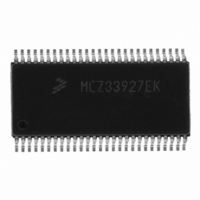
MCZ33927EK Freescale Semiconductor, MCZ33927EK Datasheet - Page 26

MCZ33927EK
Manufacturer Part Number
MCZ33927EK
Description
IC FET PRE-DRIVER 3PH 54-SOIC
Manufacturer
Freescale Semiconductor
Specifications of MCZ33927EK
Configuration
3 Phase Bridge
Input Type
Inverting and Non-Inverting
Delay Time
265ns
Current - Peak
600mA
Number Of Configurations
1
Number Of Outputs
3
High Side Voltage - Max (bootstrap)
75V
Voltage - Supply
8 V ~ 40 V
Operating Temperature
-40°C ~ 125°C
Mounting Type
Surface Mount
Package / Case
54-SOIC (7.5mm Width) Exposed Pad, 54-eSOIC, 54-HSOIC
Lead Free Status / RoHS Status
Lead free / RoHS Compliant
Available stocks
Company
Part Number
Manufacturer
Quantity
Price
DRIVER FAULT PROTECTION
against various faults. The first of them is the Current Sense
Amplifier with the Overcurrent Comparator. These two blocks
are common for all three driver phases.
Current Sense Amplifier
amplifier (see
the external FETs as a voltage across the current sense
resistor R
does not extend below ground, it is necessary to use an
external reference to permit measuring both positive and
negative currents.
microcontroller’s ADC) at the AMP_OUT pin, providing the
means for closed loop control with the 33927.
Overcurrent Comparator threshold voltage (see
Overcurrent Comparator
the pre-set threshold value by the Overcurrent Comparator
input. If the Current Sense Amplifier output voltage exceeds
the threshold of the Overcurrent Comparator it would change
the status of its output (OC_OUT pin) and the fault condition
would be latched (see
return value of the Status Register 0. If the proper Interrupt
Mask has been set, this fault condition will generate an
interrupt - the INT pin will be asserted High. The INT will be
held in the High state until the fault is removed, and the
appropriate bit in the Status Register 0 is cleared by the
CLINT0 command. This fault reporting technique is
described in detail in the
section.
Desaturation Detector
the output driver of each phase channel. It provides an
additional means to protect against “Short-to-Ground” fault
condition when the output node gets shorted to the supply
voltage (short across the high-side FET).
26
33927
FUNCTIONAL INTERNAL BLOCK DESCRIPTION
INTRODUCTION
The 33927 IC integrates several protection mechanisms
This amplifier is usually connected as a differential
The amplifier output can be monitored directly (e.g. by the
The output voltage is internally compared with the
The amplified voltage across the Rsense is compared with
The occurrence of this fault would be signalled by the
The Desaturation Detector is a comparator integrated into
SENSE
Figure
. Since the amplifier common mode range
9). It senses a current flowing through
Figure
Logic Commands and Registers
15).
Figure
17).
will be commanded ON after the end of the deadtime. The
deadtime period starts when the low-side is commanded
OFF. If the voltage at P
after the blanking time (t
initiated. An additional 1ms digital filter is applied from the
initiation of the desaturation fault before it is registered, and
all phase drivers are turned OFF (placed in a high impedance
state). If the desaturation fault condition clears before the
filter time expires, the fault is ignored and the filter timer
resets.
can be retrieved by way of the SPI. Additional SPI commands
will mask the INT flag and disable output stage shutdown,
due to desaturation and phase errors. See the
Commands and Registers
behavior and disabling the protective function.
When switching from low-side to high-side, the high-side
Valid faults are registered in the fault status register, which
Figure 13. Short to Ground Detection
Analog Integrated Circuit Device Data
X-HS_S
BLANK
section for details on masking INT
) a desaturation fault is
is less than 1.4V below V
Freescale Semiconductor
Logic
BAT


