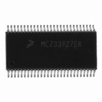
MCZ33927EK Freescale Semiconductor, MCZ33927EK Datasheet - Page 22

MCZ33927EK
Manufacturer Part Number
MCZ33927EK
Description
IC FET PRE-DRIVER 3PH 54-SOIC
Manufacturer
Freescale Semiconductor
Specifications of MCZ33927EK
Configuration
3 Phase Bridge
Input Type
Inverting and Non-Inverting
Delay Time
265ns
Current - Peak
600mA
Number Of Configurations
1
Number Of Outputs
3
High Side Voltage - Max (bootstrap)
75V
Voltage - Supply
8 V ~ 40 V
Operating Temperature
-40°C ~ 125°C
Mounting Type
Surface Mount
Package / Case
54-SOIC (7.5mm Width) Exposed Pad, 54-eSOIC, 54-HSOIC
Lead Free Status / RoHS Status
Lead free / RoHS Compliant
Available stocks
Company
Part Number
Manufacturer
Quantity
Price
PHASE C LOW-SIDE GATE (PC_LS_G)
It provides a high current with a low impedance to turn on and
off the low side FET. A low impedance drive ensures
transient currents do not overcome an off-state driver and
allow pulses of current to flow in the external FET. This output
has been designed to resist the influence of negative currents
also.
PHASE C HIGH-SIDE SOURCE (PC_HS_S)
FET is the reference voltage for the gate drive on the high
side FET and also the low voltage end of the bootstrap
capacitor.
PHASE C HIGH-SIDE GATE (PC_HS_G)
This pin provides the gate bias to turn the external FET on or
off. The gate voltage is limited to about 15V above the FET
source voltage. A low impedance drive is used, ensuring
transient currents do not overcome an off-state driver and
allow pulses of current to flow in the external FETs. This
output has been designed to resist the influence of negative
currents also.
PHASE C BOOTSTRAP (PC_BOOT)
capacitor (typically 0.1µF) connected between PC_HS_S
and this pin provides the gate voltage and current to drive the
external FET gate. The voltage across this capacitor is limited
to about 15V.
PHASE B GROUND (PGNDB)
gate currents from the low side FET. Best performance is
normally realized by connecting this node directly to the
source of the low side FET for phase B.
PHASE B LOW-SIDE GATE (PC_LS_G)
It provides a high current with a low impedance to turn on and
off the low side FET. A low impedance drive ensures
transient currents do not overcome an off-state driver and
allow pulses of current to flow in the external FET. This output
has been designed to resist the influence of negative currents
also.
PHASE B HIGH-SIDE SOURCE (PB_HS_S)
FET is the reference voltage for the gate drive on the high
side FET and also the low voltage end of the bootstrap
capacitor.
22
33927
FUNCTIONAL DESCRIPTIONS
INTRODUCTION
This is the gate drive for the phase C low side output FET.
The source connection for the phase C high side output
This is the gate drive for the phase C high side output FET.
This is the bootstrap capacitor connection for phase C. A
The phase B power ground is the pin used to return the
This is the gate drive for the phase B low side output FET.
The source connection for the phase B high side output
PHASE B HIGH-SIDE GATE (PB_HS_G)
This pin provides the gate bias to turn the external FET on or
off. The gate voltage is limited to about 15V above the FET
source voltage. A low impedance drive is used, ensuring
transient currents do not overcome an off-state driver and
allow pulses of current to flow in the external FETs. This
output has been designed to resist the influence of negative
currents also.
PHASE B BOOTSTRAP (PB_BOOT)
capacitor (typically 0.1µF) connected between PB_HS_S and
this pin provides the gate voltage and current to drive the
external FET gate. The voltage across this capacitor is limited
to about 15V.
PHASE A GROUND (PGNDA)
gate currents from the low side FET. Best performance is
normally realized by connecting this node directly to the
source of the low side FET for phase A.
PHASE A LOW-SIDE GATE (PA_LS_G)
It provides a high current with a low impedance to turn on and
off the low side FET. A low impedance drive ensures
transient currents do not overcome an off-state driver and
allow pulses of current to flow in the external FET. This output
has been designed to resist the influence of negative currents
also.
PHASE A HIGH-SIDE SOURCE (PA_HS_S)
FET is the reference voltage for the gate drive on the high
side FET and also the low voltage end of the bootstrap
capacitor.
PHASE A HIGH-SIDE GATE (PA_HS_G)
This pin provides the gate bias to turn the external FET on or
off. The gate voltage is limited to about 15V above the FET
source voltage. A low impedance drive is used, ensuring
transient currents do not overcome an off-state driver and
allow pulses of current to flow in the external FETs. This
output has been designed to resist the influence of negative
currents also.
PHASE A BOOTSTRAP (PA_BOOT)
capacitor (typically 0.1µF) connected between PA_HS_S and
this pin provides the gate voltage and current to drive the
external FET gate. The voltage across this capacitor is limited
to about 15V.
This is the gate drive for the phase B high side output FET.
This is the bootstrap capacitor connection for phase B. A
The phase A power ground is the pin used to return the
This is the gate drive for the phase A low side output FET.
The source connection for the phase A high side output
This is the gate drive for the phase A high side output FET.
This is the bootstrap capacitor connection for phase A. A
Analog Integrated Circuit Device Data
Freescale Semiconductor


