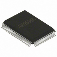
EPC4QC100N Altera, EPC4QC100N Datasheet - Page 26

EPC4QC100N
Manufacturer Part Number
EPC4QC100N
Description
IC CONFIG DEVICE 4MBIT 100-PQFP
Manufacturer
Altera
Series
EPCr
Specifications of EPC4QC100N
Programmable Type
In System Programmable
Memory Size
4Mb
Voltage - Supply
3 V ~ 3.6 V
Operating Temperature
0°C ~ 70°C
Package / Case
100-MQFP, 100-PQFP
Memory Type
Flash
Clock Frequency
66.7MHz
Supply Voltage Range
3V To 3.6V
Memory Case Style
QFP
No. Of Pins
100
Operating Temperature Range
0°C To +70°C
Access Time
90ns
Rohs Compliant
Yes
Lead Free Status / RoHS Status
Lead free / RoHS Compliant
Other names
544-1378
EPC4QC100N
EPC4QC100N
Available stocks
Company
Part Number
Manufacturer
Quantity
Price
Company:
Part Number:
EPC4QC100N
Manufacturer:
ALTERA
Quantity:
25
Company:
Part Number:
EPC4QC100N
Manufacturer:
Altera
Quantity:
135
Company:
Part Number:
EPC4QC100N
Manufacturer:
ALTERA32EOL
Quantity:
135
1–26
Programming and Configuration File Support
Volume 2: Configuration Handbook
f
1
Power up needs to be controlled so that the enhanced configuration device’s OE signal
goes high after the CONF_DONE signal is pulled low. If the EEPC device exits POR before
the FPGA is powered up, the CONF_DONE signal will be high because the pull-up
resistor is holding this signal high. When the enhanced configuration device exits
POR, OE is released and pulled high by a pull-up resistor. Since the enhanced
configuration device samples the nCS signal on the rising edge of OE, it detects a high
level on CONF_DONE and enters an idle mode. DATA and DCLK outputs will not toggle in
this state and configuration will not begin. The enhanced configuration device will
only exit this mode if it is powered down and then powered up correctly.
To ensure the enhanced configuration device enters configuration mode properly, you
must ensure that the FPGA completes power-up before the enhanced configuration
device exits POR.
The pin-selectable POR time feature is useful for ensuring this power-up sequence.
The enhanced configuration device has two POR settings, 2 ms when PORSEL is set to a
high level and 100 ms when PORSEL is set to a low level. For more margin, the
100-ms setting can be selected to allow the FPGA to power-up before configuration is
attempted.
Alternatively, a power-monitoring circuit or a power-good signal can be used to keep
the FPGA’s nCONFIG pin asserted low until both supplies have stabilized. This ensures
the correct power up sequence for successful configuration.
The Quartus II software provides programming support for the enhanced
configuration device and automatically generates the .pof for the EPC4, EPC8, and
EPC16 devices. In a multi-device project, the software can combine the .sof for
multiple ACEX 1K, APEX 20K, APEX II, Cyclone series, FLEX 10K, Mercury, and
Stratix series FPGAs into one programming file for the enhanced configuration
device.
For details about generating programming files, refer to the
Configuration Devices
Configuration Handbook.
Enhanced configuration devices can be programmed in-system through the
industry-standard 4-pin JTAG interface. The ISP feature in the enhanced
configuration device provides ease in prototyping and updating FPGA functionality.
After programming an enhanced configuration device in-system, FPGA configuration
can be initiated by including the enhanced configuration device’s JTAG INIT_CONF
instruction
(Table
1–11).
chapter and the
Chapter 1: Enhanced Configuration Devices (EPC4, EPC8, and EPC16) Data Sheet
Software Settings
Programming and Configuration File Support
section in volume 2 of the
Altera Enhanced
June 2011 Altera Corporation


