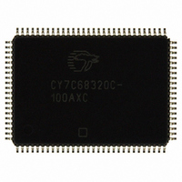
CY7C68320C-100AXC Cypress Semiconductor Corp, CY7C68320C-100AXC Datasheet - Page 21

CY7C68320C-100AXC
Manufacturer Part Number
CY7C68320C-100AXC
Description
IC USB 2.0 BRIDGE AT2LP 100LQFP
Manufacturer
Cypress Semiconductor Corp
Series
EZ-USB AT2LP™r
Type
USB to ATA Bridger
Datasheet
1.CY7C68300C-56PVXC.pdf
(42 pages)
Specifications of CY7C68320C-100AXC
Package / Case
100-LQFP
Controller Type
USB 2.0 Controller
Interface
I²C
Voltage - Supply
3 V ~ 3.6 V
Current - Supply
50mA
Operating Temperature
0°C ~ 70°C
Mounting Type
Surface Mount
Operating Supply Voltage
3.3 V
Supply Current
50 mA
Maximum Operating Temperature
+ 70 C
Minimum Operating Temperature
0 C
Mounting Style
SMD/SMT
Lead Free Status / RoHS Status
Lead free / RoHS Compliant
For Use With
CY4615B - KIT USB TO ATA REFERENCE DESIGN
Lead Free Status / Rohs Status
Lead free / RoHS Compliant
Other names
428-2267
CY7C68320C-100AXC
CY7C68320C-100AXC
Available stocks
Company
Part Number
Manufacturer
Quantity
Price
Company:
Part Number:
CY7C68320C-100AXC
Manufacturer:
Cypress
Quantity:
151
Company:
Part Number:
CY7C68320C-100AXC
Manufacturer:
Cypress Semiconductor Corp
Quantity:
10 000
EEPROM Organization
The contents of the recommended 256-byte (2048-bit) I
EEPROM are arranged as follows. In
labeled ‘Required Contents’ contains the values that must be
used for proper operation of the AT2LP. The column labeled
‘Variable Contents’ contains suggested entries and values that
may vary (such as string lengths) according to the EEPROM
data. Some values, such as the Vendor ID, Product ID and
device serial number, must be customized to meet USB
compliance. The ‘AT2LP Blaster’ tool in the CY4615C kit can be
used to edit and program these values into an AT2LP-based
product (refer to
Document 001-05809 Rev. *B
Figure
11). The ‘AT2LP Primer’ tool can be used
Figure 11. Snapshot of ‘AT2LP Blaster’ Utility
Table
11, the column
2
C
to program AT2LP-based products in a manufacturing
environment and provides for serial number randomization. See
“Board Manufacturing Test Mode”
to use vendor-specific ATAPI commands to read and program
the EEPROM.
The address pins on the serial EEPROM must be set such that
the EEPROM is at physical address 2 (A0 = 0, A1 = 1, A2 = 0)
or address 4 (A0 = 0, A1 = 0, A2 = 1) for EEPROM devices that
are internally byte-addressed memories. It is recommended that
the address pins be set this way even on EEPROMs that may
indicate that the address pins are internal no-connects.
CY7C68300C, CY7C68301C
CY7C68320C, CY7C68321C
on page 19 for details on how
Page 21 of 42
[+] Feedback


