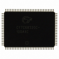
CY7C68320C-100AXC Cypress Semiconductor Corp, CY7C68320C-100AXC Datasheet - Page 15

CY7C68320C-100AXC
Manufacturer Part Number
CY7C68320C-100AXC
Description
IC USB 2.0 BRIDGE AT2LP 100LQFP
Manufacturer
Cypress Semiconductor Corp
Series
EZ-USB AT2LP™r
Type
USB to ATA Bridger
Datasheet
1.CY7C68300C-56PVXC.pdf
(42 pages)
Specifications of CY7C68320C-100AXC
Package / Case
100-LQFP
Controller Type
USB 2.0 Controller
Interface
I²C
Voltage - Supply
3 V ~ 3.6 V
Current - Supply
50mA
Operating Temperature
0°C ~ 70°C
Mounting Type
Surface Mount
Operating Supply Voltage
3.3 V
Supply Current
50 mA
Maximum Operating Temperature
+ 70 C
Minimum Operating Temperature
0 C
Mounting Style
SMD/SMT
Lead Free Status / RoHS Status
Lead free / RoHS Compliant
For Use With
CY4615B - KIT USB TO ATA REFERENCE DESIGN
Lead Free Status / Rohs Status
Lead free / RoHS Compliant
Other names
428-2267
CY7C68320C-100AXC
CY7C68320C-100AXC
Available stocks
Company
Part Number
Manufacturer
Quantity
Price
Company:
Part Number:
CY7C68320C-100AXC
Manufacturer:
Cypress
Quantity:
151
Company:
Part Number:
CY7C68320C-100AXC
Manufacturer:
Cypress Semiconductor Corp
Quantity:
10 000
RESET#
Asserting RESET# for 10 ms resets the entire AT2LP. In
self-powered designs, this pin is normally tied to V
100k resistor, and to GND through a 0.1 μF capacitor, as shown
in
Cypress does not recommend an RC reset circuit for
bus-powered devices because of the potential for VBUS voltage
drop, which may result in a startup time that exceeds the USB
limit.
FX2™/AT2™/SX2™ Reset and Power Considerations, at
www.cypress.com, for more information.
While the AT2LP is in reset, all pins are held at their default
startup state.
Figure 9. R/C Reset Circuit for Self-Powered Designs
Table 5. HID Data Bitmap
Functional Overview
Chip functionally is described in the subsequent sections.
USB Signaling Speed
AT2LP operates at the following two rates defined in the USB
Specification Revision 2.0 dated April 27, 2000:
■
■
AT2LP does not operate at the low-speed signaling rate of 1.5
Mbits/sec.
ATA Interface
The ATA/ATAPI port on the AT2LP is compatible with the Infor-
mation Technology–AT Attachment with Packet Interface–6
(ATA/ATAPI-6) Specification, T13/1410D Rev 2a. The AT2LP
supports both ATAPI packet commands as well as ATA
commands (by use of ATA Command Blocks), as outlined in
“ATA Command Block (ATACB)”
Mass Storage Class (MSC) Bulk Only Transport (BOT) Specifi-
cation
Document 001-05809 Rev. *B
Full speed, with a signaling bit rate of 12 Mbits/sec.
High speed, with a signaling bit rate of 480 Mbits/sec.
Figure
7
Refer
for
9.
6
information
to
100KΩ
0.1μF
USB Interrupt Data Byte 1
5
the
application
4
on
Command
on page 15. Refer to the USB
RESET#
3
note
2
Block
titled
CC
1
formatting.
through a
EZ-USB
0
7
HID Functions for Button Controls
Cypress’s CY7C68320C/CY7C68321C has the capability of
supporting Human Interface Device (HID) signaling to the host.
If there is a HID descriptor in the configuration data, the GPIO
pins that are set as inputs are polled by the AT2LP logic approx-
imately every 17 ms (depending on other internal interrupt
routines). If a change is detected in the state of any HID-enabled
GPIO, an HID report is sent through EP1 to the host. The report
format for byte 0 and byte 1 are shown in
The ability to add buttons to a mass storage solution opens new
applications for data backup and other device-side notification to
the host. The AT2LP Blaster software, found in the CY4615C
files, provides an easy way to enable and modify the HID
features of the AT2LP.
GPIO pins can be individually set as inputs or outputs, with byte
0x09 of the configuration data, enabling a mix of HID and general
purpose outputs. GPIOs that are not configured as inputs are
reported with a value of ‘0’ in the HID data. The RESERVED bits’
values must be ignored, and Cypress recommends using a
bitmask in software to filter out unused HID data.
Note that if using the 56-pin package, the reported GPIO[5:3]
values must be ignored because the pins are not actually
present.
Additionally, the AT2LP translates ATAPI SFF-8070i commands
to ATA commands for seamless integration of ATA devices with
generic Mass Storage Class BOT drivers.
ATA Command Block (ATACB)
The ATA Command Block (ATACB) functionality provides a
means of passing ATA commands and ATA register accesses to
the attached device for execution. ATACB commands are trans-
ferred in the Command Block Wrapper Command Block
(CBWCB) portion of the Command Block Wrapper (CBW). The
ATACB is distinguished from other command blocks by having
the first two bytes of the command block match the bVSCBSig-
nature and bVSCBSubCommand values that are defined in
Table
nature and bVSCBSubCommand are interpreted as ATA
Command Blocks. All other fields of the CBW and restrictions on
the CBWCB remain as defined in the USB Mass Storage Class
Bulk-Only Transport Specification. The ATACB must be 16 bytes
in length. The following table and text defines the fields of the
ATACB.
6. Only command blocks that have a valid bVSCBSig-
6
USB Interrupt Data Byte 0
5
CY7C68300C, CY7C68301C
CY7C68320C, CY7C68321C
4
3
2
Table
1
5.
Page 15 of 42
0
[+] Feedback


