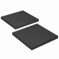
EP1S20F672I7 Altera, EP1S20F672I7 Datasheet - Page 82

EP1S20F672I7
Manufacturer Part Number
EP1S20F672I7
Description
IC STRATIX FPGA 20K LE 672-FBGA
Manufacturer
Altera
Series
Stratix®r
Datasheet
1.EP1S10F780C7.pdf
(276 pages)
Specifications of EP1S20F672I7
Number Of Logic Elements/cells
18460
Number Of Labs/clbs
1846
Total Ram Bits
1669248
Number Of I /o
426
Voltage - Supply
1.425 V ~ 1.575 V
Mounting Type
Surface Mount
Operating Temperature
-40°C ~ 100°C
Package / Case
672-FBGA
Family Name
Stratix
Number Of Logic Blocks/elements
18460
# I/os (max)
426
Frequency (max)
420.17MHz
Process Technology
0.13um (CMOS)
Operating Supply Voltage (typ)
1.5V
Logic Cells
18460
Ram Bits
1669248
Operating Supply Voltage (min)
1.425V
Operating Supply Voltage (max)
1.575V
Operating Temp Range
-40C to 100C
Operating Temperature Classification
Industrial
Mounting
Surface Mount
Pin Count
672
Package Type
FBGA
Lead Free Status / RoHS Status
Contains lead / RoHS non-compliant
Number Of Gates
-
Lead Free Status / Rohs Status
Not Compliant
Available stocks
Company
Part Number
Manufacturer
Quantity
Price
Part Number:
EP1S20F672I7
Manufacturer:
ALTERA/阿尔特拉
Quantity:
20 000
Company:
Part Number:
EP1S20F672I7N
Manufacturer:
ALTERA20
Quantity:
212
- Current page: 82 of 276
- Download datasheet (4Mb)
Digital Signal Processing Block
2–68
Stratix Device Handbook, Volume 1
single DSP block can implement two sums or differences from two
18 × 18-bit multipliers each or four sums or differences from two 9 × 9-bit
multipliers each.
You can use the two-multipliers adder mode for complex multiplications,
which are written as:
The two-multipliers adder mode allows a single DSP block to calculate
the real part [(a × c) – (b × d)] using one subtractor and the imaginary part
[(a × d) + (b × c)] using one adder, for data widths up to 18 bits. Two
complex multiplications are possible for data widths up to 9 bits using
four adder/subtractor/accumulator blocks.
two-multipliers adder.
Figure 2–38. Two-Multipliers Adder Mode Implementing Complex Multiply
Four-Multipliers Adder Mode
In the four-multipliers adder mode, the DSP block adds the results of two
first -stage adder/subtractor blocks. One sum of four 18 × 18-bit
multipliers or two different sums of two sets of four 9 × 9-bit multipliers
can be implemented in a single DSP block. The product width for each
multiplier must be the same size. The four-multipliers adder mode is
useful for FIR filter applications.
adder mode.
(a + jb) × (c + jd) = [(a × c) – (b × d)] + j × [(a × d) + (b × c)]
18
18
18
18
A
C
B
D
A
D
B
C
18
18
18
18
18
18
18
18
36
36
36
36
Figure 2–39
Subtractor
Adder
DSP Block
Figure 2–38
shows the four multipliers
37
37
(Imaginary Part)
(A × C) − (B × D)
(A × D) + (B × C)
(Real Part)
Altera Corporation
shows an 18-bit
July 2005
Related parts for EP1S20F672I7
Image
Part Number
Description
Manufacturer
Datasheet
Request
R

Part Number:
Description:
CYCLONE II STARTER KIT EP2C20N
Manufacturer:
Altera
Datasheet:

Part Number:
Description:
CPLD, EP610 Family, ECMOS Process, 300 Gates, 16 Macro Cells, 16 Reg., 16 User I/Os, 5V Supply, 35 Speed Grade, 24DIP
Manufacturer:
Altera Corporation
Datasheet:

Part Number:
Description:
CPLD, EP610 Family, ECMOS Process, 300 Gates, 16 Macro Cells, 16 Reg., 16 User I/Os, 5V Supply, 15 Speed Grade, 24DIP
Manufacturer:
Altera Corporation
Datasheet:

Part Number:
Description:
Manufacturer:
Altera Corporation
Datasheet:

Part Number:
Description:
CPLD, EP610 Family, ECMOS Process, 300 Gates, 16 Macro Cells, 16 Reg., 16 User I/Os, 5V Supply, 30 Speed Grade, 24DIP
Manufacturer:
Altera Corporation
Datasheet:

Part Number:
Description:
High-performance, low-power erasable programmable logic devices with 8 macrocells, 10ns
Manufacturer:
Altera Corporation
Datasheet:

Part Number:
Description:
High-performance, low-power erasable programmable logic devices with 8 macrocells, 7ns
Manufacturer:
Altera Corporation
Datasheet:

Part Number:
Description:
Classic EPLD
Manufacturer:
Altera Corporation
Datasheet:

Part Number:
Description:
High-performance, low-power erasable programmable logic devices with 8 macrocells, 10ns
Manufacturer:
Altera Corporation
Datasheet:

Part Number:
Description:
Manufacturer:
Altera Corporation
Datasheet:

Part Number:
Description:
Manufacturer:
Altera Corporation
Datasheet:

Part Number:
Description:
Manufacturer:
Altera Corporation
Datasheet:

Part Number:
Description:
CPLD, EP610 Family, ECMOS Process, 300 Gates, 16 Macro Cells, 16 Reg., 16 User I/Os, 5V Supply, 25 Speed Grade, 24DIP
Manufacturer:
Altera Corporation
Datasheet:


