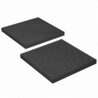
EP1S20F672I7 Altera, EP1S20F672I7 Datasheet - Page 162

EP1S20F672I7
Manufacturer Part Number
EP1S20F672I7
Description
IC STRATIX FPGA 20K LE 672-FBGA
Manufacturer
Altera
Series
Stratix®r
Datasheet
1.EP1S10F780C7.pdf
(276 pages)
Specifications of EP1S20F672I7
Number Of Logic Elements/cells
18460
Number Of Labs/clbs
1846
Total Ram Bits
1669248
Number Of I /o
426
Voltage - Supply
1.425 V ~ 1.575 V
Mounting Type
Surface Mount
Operating Temperature
-40°C ~ 100°C
Package / Case
672-FBGA
Family Name
Stratix
Number Of Logic Blocks/elements
18460
# I/os (max)
426
Frequency (max)
420.17MHz
Process Technology
0.13um (CMOS)
Operating Supply Voltage (typ)
1.5V
Logic Cells
18460
Ram Bits
1669248
Operating Supply Voltage (min)
1.425V
Operating Supply Voltage (max)
1.575V
Operating Temp Range
-40C to 100C
Operating Temperature Classification
Industrial
Mounting
Surface Mount
Pin Count
672
Package Type
FBGA
Lead Free Status / RoHS Status
Contains lead / RoHS non-compliant
Number Of Gates
-
Lead Free Status / Rohs Status
Not Compliant
Available stocks
Company
Part Number
Manufacturer
Quantity
Price
Part Number:
EP1S20F672I7
Manufacturer:
ALTERA/阿尔特拉
Quantity:
20 000
Company:
Part Number:
EP1S20F672I7N
Manufacturer:
ALTERA20
Quantity:
212
Configuration
3–8
Stratix Device Handbook, Volume 1
synthesis, allowing real-time variation of the PLL frequency and delay.
The rest of the device is functional while reconfiguring the PLL. See the
Stratix Architecture chapter of the Stratix Device Handbook, Volume 1 for
more information on Stratix PLLs.
Remote Update Configuration Modes
Stratix devices also support remote configuration using an Altera
enhanced configuration device (e.g., EPC16, EPC8, and EPC4 devices)
with page mode selection. Factory configuration data is stored in the
default page of the configuration device. This is the default configuration
that contains the design required to control remote updates and handle
or recover from errors. You write the factory configuration once into the
flash memory or configuration device. Remote update data can update
any of the remaining pages of the configuration device. If there is an error
or corruption in a remote update configuration, the configuration device
reverts back to the factory configuration information.
There are two remote configuration modes: remote and local
configuration. You can use the remote update configuration mode for all
three configuration modes: serial, parallel synchronous, and parallel
asynchronous. Configuration devices (for example, EPC16 devices) only
support serial and parallel synchronous modes. Asynchronous parallel
mode allows remote updates when an intelligent host is used to configure
the Stratix device. This host must support page mode settings similar to
an EPC16 device.
Remote Update Mode
When the Stratix device is first powered up in remote update
programming mode, it loads the configuration located at page address
“000.” The factory configuration should always be located at page
address “000,” and should never be remotely updated. The factory
configuration contains the required logic to perform the following
operations:
■
■
■
The factory configuration is the default and takes control if an error
occurs while loading the application configuration.
Determine the page address/load location for the next application’s
configuration data
Recover from a previous configuration error
Receive new configuration data and write it into the configuration
device
Altera Corporation
July 2005


