A000048 Arduino, A000048 Datasheet - Page 30
A000048
Manufacturer Part Number
A000048
Description
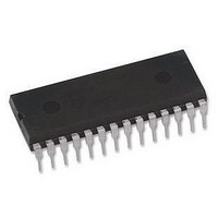
ATMEGA328 MCU IC W/ Arduino UNO Bootloader
Manufacturer
Arduino
Series
-r
Specifications of A000048
Accessory Type
Pre-Programed IC
Features
Powered Via USB Connection, AC-to-DC Adapter, Power Jack, ICSP Header
Core Processor
AVR
Core Size
8-Bit
Speed
20MHz
Connectivity
I²C, SPI, UART/USART
Peripherals
Brown-out Detect/Reset, POR, PWM, WDT
Number Of I /o
23
Program Memory Size
32KB (16K x 16)
Program Memory Type
FLASH
Eeprom Size
1K x 8
Ram Size
2K x 8
Voltage - Supply (vcc/vdd)
1.8 V ~ 5.5 V
Data Converters
A/D 8x10b
Oscillator Type
Internal
Operating Temperature
-40°C ~ 85°C
Package / Case
-
For Use With
ATmega328 Microcontrollers
Lead Free Status / RoHS Status
Lead free / RoHS Compliant
Lead Free Status / RoHS Status
Lead free / RoHS Compliant


8.4
8271C–AVR–08/10
Full Swing Crystal Oscillator
Table 8-4.
Notes:
Pins XTAL1 and XTAL2 are input and output, respectively, of an inverting amplifier which can be
configured for use as an On-chip Oscillator, as shown in
crystal or a ceramic resonator may be used.
This Crystal Oscillator is a full swing oscillator, with rail-to-rail swing on the XTAL2 output. This is
useful for driving other clock inputs and in noisy environments. The current consumption is
higher than the
Oscillator will only operate for V
C1 and C2 should always be equal for both crystals and resonators. The optimal value of the
capacitors depends on the crystal or resonator in use, the amount of stray capacitance, and the
electromagnetic noise of the environment. Some initial guidelines for choosing capacitors for
use with crystals are given in
ues given by the manufacturer should be used.
The operating mode is selected by the fuses CKSEL3...1 as shown in
Table 8-5.
Notes:
ATmega48A/48PA/88A/88PA/168A/168PA/328/328
Oscillator Source /
Power Conditions
Crystal Oscillator, BOD
enabled
Crystal Oscillator, fast
rising power
Crystal Oscillator, slowly
rising power
Frequency Range
(MHz)
1. These options should only be used when not operating close to the maximum frequency of the
2. These options are intended for use with ceramic resonators and will ensure frequency stability
1. If the cryatal frequency exceeds the specification of the device (depends on V
0.4 - 20
device, and only if frequency stability at start-up is not important for the application. These
options are not suitable for crystals.
at start-up. They can also be used with crystals when not operating close to the maximum fre-
quency of the device, and if frequency stability at start-up is not important for the application.
Fuse can be programmed in order to divide the internal frequency by 8. It must be ensured
that the resulting divided clock meets the frequency specification of the device.
Start-up Times for the Low Power Crystal Oscillator Clock Selection (Continued)
Full Swing Crystal Oscillator operating modes
”Low Power Crystal Oscillator” on page
(1)
Start-up Time from
Table 8-6 on page
Power-down and
CC
Power-save
= 2.7 - 5.5 volts.
16K CK
16K CK
16K CK
Capacitors C1 and C2 (pF)
Recommended Range for
12 - 22
31. For ceramic resonators, the capacitor val-
Additional Delay
14CK + 4.1 ms
14CK + 65 ms
(V
from Reset
Figure 8-2 on page
CC
28. Note that the Full Swing Crystal
14CK
= 5.0V)
Table
CKSEL3...1
CKSEL0
8-5.
29. Either a quartz
1
1
1
CC
011
), the CKDIV8
SUT1...0
01
10
11
30
Related parts for A000048
Image
Part Number
Description
Manufacturer
Datasheet
Request
R

Part Number:
Description:
Daughter Cards & OEM Boards ARDUINO UNO PROTO PCB REV 3
Manufacturer:
Arduino
Part Number:
Description:
Daughter Cards & OEM Boards ARDUINO SHIELD PROTO KIT REV 3
Manufacturer:
Arduino
Part Number:
Description:
Daughter Cards & OEM Boards ARDUINO MEGA PROTO KIT REV 3
Manufacturer:
Arduino
Part Number:
Description:
Daughter Cards & OEM Boards ARDUINO MEGA PROTO PCB REV 3
Manufacturer:
Arduino
Part Number:
Description:
Development Boards & Kits - AVR ARDUINO STARTER KIT W/ UNO REV3
Manufacturer:
Arduino
Part Number:
Description:
RF Development Tools ARDUINO SHIELD WIRELESS PROTO
Manufacturer:
Arduino
Datasheet:
Part Number:
Description:
RF Development Tools ARDUINO SHIELD WIRELESS WITH SD
Manufacturer:
Arduino
Datasheet:

Part Number:
Description:
Development Software Getting started w/Arduino
Manufacturer:
Arduino

Part Number:
Description:
Ethernet Modules & Development Tools Ethernet Shield for Arduino
Manufacturer:
Arduino

Part Number:
Description:
MCU, MPU & DSP Development Tools LilyPad Arduino Main Board
Manufacturer:
Arduino

Part Number:
Description:
ARDUINO NANO Board
Manufacturer:
Arduino
Datasheet:
Part Number:
Description:
Ethernet Modules & Development Tools ETHERNET SHEILD PoE FOR ARDUINO
Manufacturer:
Arduino
Datasheet:
Part Number:
Description:
KIT XBEE/SHIELD ARDUINO
Manufacturer:
Arduino
Datasheet:
Part Number:
Description:
Memory Cards MICRO SD CARD 1GB WITH SD ADAPTER
Manufacturer:
Arduino