A000048 Arduino, A000048 Datasheet - Page 223
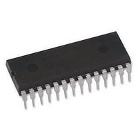
A000048
Manufacturer Part Number
A000048
Description
ATMEGA328 MCU IC W/ Arduino UNO Bootloader
Manufacturer
Arduino
Series
-r
Specifications of A000048
Accessory Type
Pre-Programed IC
Features
Powered Via USB Connection, AC-to-DC Adapter, Power Jack, ICSP Header
Core Processor
AVR
Core Size
8-Bit
Speed
20MHz
Connectivity
I²C, SPI, UART/USART
Peripherals
Brown-out Detect/Reset, POR, PWM, WDT
Number Of I /o
23
Program Memory Size
32KB (16K x 16)
Program Memory Type
FLASH
Eeprom Size
1K x 8
Ram Size
2K x 8
Voltage - Supply (vcc/vdd)
1.8 V ~ 5.5 V
Data Converters
A/D 8x10b
Oscillator Type
Internal
Operating Temperature
-40°C ~ 85°C
Package / Case
-
For Use With
ATmega328 Microcontrollers
Lead Free Status / RoHS Status
Lead free / RoHS Compliant
Lead Free Status / RoHS Status
Lead free / RoHS Compliant


21.5.3
21.5.4
21.5.5
8271C–AVR–08/10
Bus Interface Unit
Address Match Unit
Control Unit
that slaves may prolong the SCL low period, thereby reducing the average TWI bus clock
period. The SCL frequency is generated according to the following equation:
• TWBR = Value of the TWI Bit Rate Register.
• PrescalerValue = Value of the prescaler, see
Note:
This unit contains the Data and Address Shift Register (TWDR), a START/STOP Controller and
Arbitration detection hardware. The TWDR contains the address or data bytes to be transmitted,
or the address or data bytes received. In addition to the 8-bit TWDR, the Bus Interface Unit also
contains a register containing the (N)ACK bit to be transmitted or received. This (N)ACK Regis-
ter is not directly accessible by the application software. However, when receiving, it can be set
or cleared by manipulating the TWI Control Register (TWCR). When in Transmitter mode, the
value of the received (N)ACK bit can be determined by the value in the TWSR.
The START/STOP Controller is responsible for generation and detection of START, REPEATED
START, and STOP conditions. The START/STOP controller is able to detect START and STOP
conditions even when the AVR MCU is in one of the sleep modes, enabling the MCU to wake up
if addressed by a Master.
If the TWI has initiated a transmission as Master, the Arbitration Detection hardware continu-
ously monitors the transmission trying to determine if arbitration is in process. If the TWI has lost
an arbitration, the Control Unit is informed. Correct action can then be taken and appropriate
status codes generated.
The Address Match unit checks if received address bytes match the seven-bit address in the
TWI Address Register (TWAR). If the TWI General Call Recognition Enable (TWGCE) bit in the
TWAR is written to one, all incoming address bits will also be compared against the General Call
address. Upon an address match, the Control Unit is informed, allowing correct action to be
taken. The TWI may or may not acknowledge its address, depending on settings in the TWCR.
The Address Match unit is able to compare addresses even when the AVR MCU is in sleep
mode, enabling the MCU to wake up if addressed by a Master.
The Control unit monitors the TWI bus and generates responses corresponding to settings in the
TWI Control Register (TWCR). When an event requiring the attention of the application occurs
on the TWI bus, the TWI Interrupt Flag (TWINT) is asserted. In the next clock cycle, the TWI Sta-
tus Register (TWSR) is updated with a status code identifying the event. The TWSR only
contains relevant status information when the TWI Interrupt Flag is asserted. At all other times,
the TWSR contains a special status code indicating that no relevant status information is avail-
able. As long as the TWINT Flag is set, the SCL line is held low. This allows the application
software to complete its tasks before allowing the TWI transmission to continue.
The TWINT Flag is set in the following situations:
• After the TWI has transmitted a START/REPEATED START condition.
ATmega48A/48PA/88A/88PA/168A/168PA/328/328
Pull-up resistor values should be selected according to the SCL frequency and the capacitive bus
line load. See
Table 28-15 on page 326
SCL frequency
=
---------------------------------------------------------------------------------------- -
16
+
for value of pull-up resistor.
2(TWBR)
CPU Clock frequency
Table 21-7 on page
⋅
(
PrescalerValue
244.
)
223
Related parts for A000048
Image
Part Number
Description
Manufacturer
Datasheet
Request
R

Part Number:
Description:
Daughter Cards & OEM Boards ARDUINO UNO PROTO PCB REV 3
Manufacturer:
Arduino
Part Number:
Description:
Daughter Cards & OEM Boards ARDUINO SHIELD PROTO KIT REV 3
Manufacturer:
Arduino
Part Number:
Description:
Daughter Cards & OEM Boards ARDUINO MEGA PROTO KIT REV 3
Manufacturer:
Arduino
Part Number:
Description:
Daughter Cards & OEM Boards ARDUINO MEGA PROTO PCB REV 3
Manufacturer:
Arduino
Part Number:
Description:
Development Boards & Kits - AVR ARDUINO STARTER KIT W/ UNO REV3
Manufacturer:
Arduino
Part Number:
Description:
RF Development Tools ARDUINO SHIELD WIRELESS PROTO
Manufacturer:
Arduino
Datasheet:
Part Number:
Description:
RF Development Tools ARDUINO SHIELD WIRELESS WITH SD
Manufacturer:
Arduino
Datasheet:

Part Number:
Description:
Development Software Getting started w/Arduino
Manufacturer:
Arduino

Part Number:
Description:
Ethernet Modules & Development Tools Ethernet Shield for Arduino
Manufacturer:
Arduino

Part Number:
Description:
MCU, MPU & DSP Development Tools LilyPad Arduino Main Board
Manufacturer:
Arduino

Part Number:
Description:
ARDUINO NANO Board
Manufacturer:
Arduino
Datasheet:
Part Number:
Description:
Ethernet Modules & Development Tools ETHERNET SHEILD PoE FOR ARDUINO
Manufacturer:
Arduino
Datasheet:
Part Number:
Description:
KIT XBEE/SHIELD ARDUINO
Manufacturer:
Arduino
Datasheet:
Part Number:
Description:
Memory Cards MICRO SD CARD 1GB WITH SD ADAPTER
Manufacturer:
Arduino