A000048 Arduino, A000048 Datasheet - Page 157
A000048
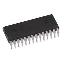
Manufacturer Part Number
A000048
Description
ATMEGA328 MCU IC W/ Arduino UNO Bootloader
Manufacturer
Arduino
Series
-r
Specifications of A000048
Accessory Type
Pre-Programed IC
Features
Powered Via USB Connection, AC-to-DC Adapter, Power Jack, ICSP Header
Core Processor
AVR
Core Size
8-Bit
Speed
20MHz
Connectivity
I²C, SPI, UART/USART
Peripherals
Brown-out Detect/Reset, POR, PWM, WDT
Number Of I /o
23
Program Memory Size
32KB (16K x 16)
Program Memory Type
FLASH
Eeprom Size
1K x 8
Ram Size
2K x 8
Voltage - Supply (vcc/vdd)
1.8 V ~ 5.5 V
Data Converters
A/D 8x10b
Oscillator Type
Internal
Operating Temperature
-40°C ~ 85°C
Package / Case
-
For Use With
ATmega328 Microcontrollers
Lead Free Status / RoHS Status
Lead free / RoHS Compliant
Lead Free Status / RoHS Status
Lead free / RoHS Compliant


17.10 Timer/Counter Prescaler
8271C–AVR–08/10
• Description of wake up from Power-save or ADC Noise Reduction mode when the timer is
• Reading of the TCNT2 Register shortly after wake-up from Power-save may give an incorrect
During asynchronous operation, the synchronization of the Interrupt Flags for the asynchronous
timer takes 3 processor cycles plus one timer cycle. The timer is therefore advanced by at least
one before the processor can read the timer value causing the setting of the Interrupt Flag. The
Output Compare pin is changed on the timer clock and is not synchronized to the processor
clock.
Figure 17-12. Prescaler for Timer/Counter2
The clock source for Timer/Counter2 is named clk
system I/O clock clk
clocked from the TOSC1 pin. This enables use of Timer/Counter2 as a Real Time Counter
ATmega48A/48PA/88A/88PA/168A/168PA/328/328
clocked asynchronously: When the interrupt condition is met, the wake up process is started
on the following cycle of the timer clock, that is, the timer is always advanced by at least one
before the processor can read the counter value. After wake-up, the MCU is halted for four
cycles, it executes the interrupt routine, and resumes execution from the instruction following
SLEEP.
result. Since TCNT2 is clocked on the asynchronous TOSC clock, reading TCNT2 must be
done through a register synchronized to the internal I/O clock domain. Synchronization takes
place for every rising TOSC1 edge. When waking up from Power-save mode, and the I/O clock
(clk
until the next rising TOSC1 edge. The phase of the TOSC clock after waking up from Power-
save mode is essentially unpredictable, as it depends on the wake-up time. The recommended
procedure for reading TCNT2 is thus as follows:
a. Write any value to either of the registers OCR2x or TCCR2x.
b. Wait for the corresponding Update Busy Flag to be cleared.
c. Read TCNT2.
I/O
PSRASY
) again becomes active, TCNT2 will read as the previous value (before entering sleep)
TOSC1
clk
CS20
CS21
CS22
AS2
I/O
IO
. By setting the AS2 bit in ASSR, Timer/Counter2 is asynchronously
clk
T2S
Clear
TIMER/COUNTER2 CLOCK SOURCE
T2S
0
. clk
10-BIT T/C PRESCALER
T2S
clk
T2
is by default connected to the main
157
Related parts for A000048
Image
Part Number
Description
Manufacturer
Datasheet
Request
R

Part Number:
Description:
Daughter Cards & OEM Boards ARDUINO UNO PROTO PCB REV 3
Manufacturer:
Arduino
Part Number:
Description:
Daughter Cards & OEM Boards ARDUINO SHIELD PROTO KIT REV 3
Manufacturer:
Arduino
Part Number:
Description:
Daughter Cards & OEM Boards ARDUINO MEGA PROTO KIT REV 3
Manufacturer:
Arduino
Part Number:
Description:
Daughter Cards & OEM Boards ARDUINO MEGA PROTO PCB REV 3
Manufacturer:
Arduino
Part Number:
Description:
Development Boards & Kits - AVR ARDUINO STARTER KIT W/ UNO REV3
Manufacturer:
Arduino
Part Number:
Description:
RF Development Tools ARDUINO SHIELD WIRELESS PROTO
Manufacturer:
Arduino
Datasheet:
Part Number:
Description:
RF Development Tools ARDUINO SHIELD WIRELESS WITH SD
Manufacturer:
Arduino
Datasheet:

Part Number:
Description:
Development Software Getting started w/Arduino
Manufacturer:
Arduino

Part Number:
Description:
Ethernet Modules & Development Tools Ethernet Shield for Arduino
Manufacturer:
Arduino

Part Number:
Description:
MCU, MPU & DSP Development Tools LilyPad Arduino Main Board
Manufacturer:
Arduino

Part Number:
Description:
ARDUINO NANO Board
Manufacturer:
Arduino
Datasheet:
Part Number:
Description:
Ethernet Modules & Development Tools ETHERNET SHEILD PoE FOR ARDUINO
Manufacturer:
Arduino
Datasheet:
Part Number:
Description:
KIT XBEE/SHIELD ARDUINO
Manufacturer:
Arduino
Datasheet:
Part Number:
Description:
Memory Cards MICRO SD CARD 1GB WITH SD ADAPTER
Manufacturer:
Arduino