A000048 Arduino, A000048 Datasheet - Page 182
A000048
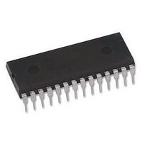
Manufacturer Part Number
A000048
Description
ATMEGA328 MCU IC W/ Arduino UNO Bootloader
Manufacturer
Arduino
Series
-r
Specifications of A000048
Accessory Type
Pre-Programed IC
Features
Powered Via USB Connection, AC-to-DC Adapter, Power Jack, ICSP Header
Core Processor
AVR
Core Size
8-Bit
Speed
20MHz
Connectivity
I²C, SPI, UART/USART
Peripherals
Brown-out Detect/Reset, POR, PWM, WDT
Number Of I /o
23
Program Memory Size
32KB (16K x 16)
Program Memory Type
FLASH
Eeprom Size
1K x 8
Ram Size
2K x 8
Voltage - Supply (vcc/vdd)
1.8 V ~ 5.5 V
Data Converters
A/D 8x10b
Oscillator Type
Internal
Operating Temperature
-40°C ~ 85°C
Package / Case
-
For Use With
ATmega328 Microcontrollers
Lead Free Status / RoHS Status
Lead free / RoHS Compliant
Lead Free Status / RoHS Status
Lead free / RoHS Compliant


19.4.1
8271C–AVR–08/10
Parity Bit Calculation
A frame starts with the start bit followed by the least significant data bit. Then the next data bits,
up to a total of nine, are succeeding, ending with the most significant bit. If enabled, the parity bit
is inserted after the data bits, before the stop bits. When a complete frame is transmitted, it can
be directly followed by a new frame, or the communication line can be set to an idle (high) state.
Figure 19-4
optional.
Figure 19-4. Frame Formats
The frame format used by the USART is set by the UCSZn2:0, UPMn1:0 and USBSn bits in
UCSRnB and UCSRnC. The Receiver and Transmitter use the same setting. Note that changing
the setting of any of these bits will corrupt all ongoing communication for both the Receiver and
Transmitter.
The USART Character SiZe (UCSZn2:0) bits select the number of data bits in the frame. The
USART Parity mode (UPMn1:0) bits enable and set the type of parity bit. The selection between
one or two stop bits is done by the USART Stop Bit Select (USBSn) bit. The Receiver ignores
the second stop bit. An FE (Frame Error) will therefore only be detected in the cases where the
first stop bit is zero.
The parity bit is calculated by doing an exclusive-or of all the data bits. If odd parity is used, the
result of the exclusive or is inverted. The relation between the parity bit and data bits is as
follows:
If used, the parity bit is located between the last data bit and first stop bit of a serial frame.
ATmega48A/48PA/88A/88PA/168A/168PA/328/328
St
(n)
P
Sp
IDLE
P
P
d
even
odd
n
illustrates the possible combinations of the frame formats. Bits inside brackets are
(IDLE)
Start bit, always low.
Data bits (0 to 8).
Parity bit. Can be odd or even.
Stop bit, always high.
No transfers on the communication line (RxDn or TxDn). An IDLE line must be
high.
Parity bit using even parity
Parity bit using odd parity
Data bit n of the character
St
P
0
P
even
odd
1
=
=
d
d
2
n 1
n 1
–
–
3
⊕
⊕
…
…
4
⊕
⊕
FRAME
[5]
d
d
3
3
⊕
⊕
[6]
d
d
2
2
⊕
⊕
[7]
d
d
1
1
[8]
⊕
⊕
d
d
0
0
[P]
⊕
⊕
0
1
Sp1 [Sp2]
(St / IDLE)
182
Related parts for A000048
Image
Part Number
Description
Manufacturer
Datasheet
Request
R

Part Number:
Description:
Daughter Cards & OEM Boards ARDUINO UNO PROTO PCB REV 3
Manufacturer:
Arduino
Part Number:
Description:
Daughter Cards & OEM Boards ARDUINO SHIELD PROTO KIT REV 3
Manufacturer:
Arduino
Part Number:
Description:
Daughter Cards & OEM Boards ARDUINO MEGA PROTO KIT REV 3
Manufacturer:
Arduino
Part Number:
Description:
Daughter Cards & OEM Boards ARDUINO MEGA PROTO PCB REV 3
Manufacturer:
Arduino
Part Number:
Description:
Development Boards & Kits - AVR ARDUINO STARTER KIT W/ UNO REV3
Manufacturer:
Arduino
Part Number:
Description:
RF Development Tools ARDUINO SHIELD WIRELESS PROTO
Manufacturer:
Arduino
Datasheet:
Part Number:
Description:
RF Development Tools ARDUINO SHIELD WIRELESS WITH SD
Manufacturer:
Arduino
Datasheet:

Part Number:
Description:
Development Software Getting started w/Arduino
Manufacturer:
Arduino

Part Number:
Description:
Ethernet Modules & Development Tools Ethernet Shield for Arduino
Manufacturer:
Arduino

Part Number:
Description:
MCU, MPU & DSP Development Tools LilyPad Arduino Main Board
Manufacturer:
Arduino

Part Number:
Description:
ARDUINO NANO Board
Manufacturer:
Arduino
Datasheet:
Part Number:
Description:
Ethernet Modules & Development Tools ETHERNET SHEILD PoE FOR ARDUINO
Manufacturer:
Arduino
Datasheet:
Part Number:
Description:
KIT XBEE/SHIELD ARDUINO
Manufacturer:
Arduino
Datasheet:
Part Number:
Description:
Memory Cards MICRO SD CARD 1GB WITH SD ADAPTER
Manufacturer:
Arduino