8808A/SU 120V Fluke Electronics, 8808A/SU 120V Datasheet - Page 9
8808A/SU 120V
Manufacturer Part Number
8808A/SU 120V
Description
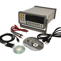
USB CABLE KIT SW DMM 5.5 RES
Manufacturer
Fluke Electronics
Type
Digital (DMM)r
Datasheet
1.8808A_120V.pdf
(100 pages)
Specifications of 8808A/SU 120V
Includes
Test Leads
Style
Bench
Display Digits
5.5
Display Type
VFD, Dual
Display Count
200000
Function
Voltage, Current, Resistance, Frequency
Functions, Extra
Continuity, dB, Diode Test
Features
Hold, Min/Max, RS-232 Port
Ranging
Auto/Manual
Response
True RMS
Lead Free Status / RoHS Status
Not applicable / RoHS non-compliant
Other names
614-1069


2-1.
2-2.
2-3.
2-4.
2-5.
3-1.
3-2.
3-3.
3-4.
3-5.
3-6.
3-7.
3-8.
3-9.
3-10. Continuity Test....................................................................................................... 3-15
3-11. Diode Test .............................................................................................................. 3-16
3-12. External Trigger Circuit ......................................................................................... 3-17
4-1.
4-2.
4-3.
4-4.
A-1. Example of Dual Display Showing Volts AC and Frequency ............................... A-2
A-2. DC Voltage and DC Current Measurement on Input Signal.................................. A-4
A-3. Shunt Method of Low-Level Current Measurement .............................................. A-8
A-4. Zero Burden Voltage Low-Level Current Measurement ....................................... A-8
B-1. 2X4 Wire Test Leads ............................................................................................. B-2
Replacing the Line Power Fuse.............................................................................. 2-5
Replacing the Current-Input Fuses......................................................................... 2-6
Line-Power Cord Types Available from Fluke...................................................... 2-7
Bail Adjustment and Removal ............................................................................... 2-8
Boot removal.......................................................................................................... 2-9
Front Panel ............................................................................................................. 3-4
Display Annunciators and Indicators ..................................................................... 3-6
Rear Panel .............................................................................................................. 3-8
Voltage and Frequency Measurement.................................................................... 3-10
2-Wire Resistance Measurement............................................................................ 3-11
4-Wire Resistance Measurement............................................................................ 3-12
Input Connections for 4-wire ohms using 2x4 wire leads...................................... 3-13
Current Measurement <200 mA............................................................................. 3-14
Current Measurement 200 mA to 10 A .................................................................. 3-14
External Trigger Using Pin 9 of RS-232 Interface................................................. 4-10
Overview of Status Data Structures ....................................................................... 4-12
Event Status and Event Status Enable Registers .................................................... 4-13
Sample Program for RS-232 Computer Interface .................................................. 4-28
vii
List of Figures