8808A/SU 120V Fluke Electronics, 8808A/SU 120V Datasheet - Page 4
8808A/SU 120V
Manufacturer Part Number
8808A/SU 120V
Description
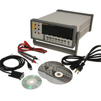
USB CABLE KIT SW DMM 5.5 RES
Manufacturer
Fluke Electronics
Type
Digital (DMM)r
Datasheet
1.8808A_120V.pdf
(100 pages)
Specifications of 8808A/SU 120V
Includes
Test Leads
Style
Bench
Display Digits
5.5
Display Type
VFD, Dual
Display Count
200000
Function
Voltage, Current, Resistance, Frequency
Functions, Extra
Continuity, dB, Diode Test
Features
Hold, Min/Max, RS-232 Port
Ranging
Auto/Manual
Response
True RMS
Lead Free Status / RoHS Status
Not applicable / RoHS non-compliant
Other names
614-1069


8808A
Users Manual
3
4
Storing and Shipping the Meter ......................................................................... 2-3
Power Considerations ........................................................................................ 2-3
Connecting to Line Power ................................................................................. 2-7
Turning Power On ............................................................................................. 2-8
Adjusting the Bail .............................................................................................. 2-8
Installing the Meter into an Equipment Rack .................................................... 2-8
Cleaning the Meter............................................................................................. 2-9
Fluke 45 Emulation............................................................................................ 2-9
Illuminating All Display Segments.................................................................... 2-10
Operating the Meter from the Front Panel ........................................ 3-1
Introduction........................................................................................................ 3-3
Dual Display ...................................................................................................... 3-6
Rear Panel .......................................................................................................... 3-8
Adjusting Meter Range ...................................................................................... 3-8
Selecting a Measurement Rate........................................................................... 3-9
Selecting a Measurement Function.................................................................... 3-9
Selecting a Function Modifier ........................................................................... 3-17
Compare Function (COMP)............................................................................... 3-22
List and Number Editors.................................................................................... 3-22
Function Keys S1 – S6....................................................................................... 3-24
Power-Up Configuration.................................................................................... 3-25
Calibration ......................................................................................................... 3-26
Operating the Meter Using the Computer Interface ......................... 4-1
Selecting the Line Voltage ............................................................................ 2-4
Replacing the Fuses....................................................................................... 2-4
Primary Display............................................................................................. 3-6
Secondary Display......................................................................................... 3-6
Measuring Voltage ........................................................................................ 3-10
Measuring Frequency .................................................................................... 3-10
Frequency Ranging........................................................................................ 3-11
Measuring Resistance .................................................................................... 3-11
Measuring Current......................................................................................... 3-13
Automatic Input Terminal Detection............................................................. 3-14
Diode / Continuity Testing ............................................................................ 3-15
Making a Triggered Measurement ................................................................ 3-16
Relative Readings Modifier (REL)................................................................ 3-18
Decibels and Auto Power Modifier ............................................................... 3-18
Touch Hold Function (HOLD) ...................................................................... 3-19
Minimum / Maximum Modifier (MIN MAX) .............................................. 3-20
Using the Function Modifiers in Combination.............................................. 3-21
Second Level Operations (Using the SHIFT Button).................................... 3-21
Setting the Compare Range ........................................................................... 3-22
Using the Compare Function......................................................................... 3-22
Using the List Editor ..................................................................................... 3-23
Using the Number Editor............................................................................... 3-24
Factory Settings of Power-Up Configuration ................................................ 3-25
Line-Power Fuse ....................................................................................... 2-4
Current-Input Fuses................................................................................... 2-5
2-Wire Resistance Measurement............................................................... 3-11
4-Wire Resistance Measurement............................................................... 3-12
Setting the Trigger Mode .......................................................................... 3-16
Connecting to an External Trigger ............................................................ 3-16
ii