8808A/SU 120V Fluke Electronics, 8808A/SU 120V Datasheet - Page 59
8808A/SU 120V
Manufacturer Part Number
8808A/SU 120V
Description
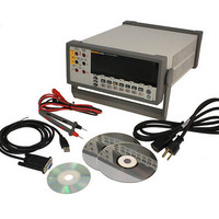
USB CABLE KIT SW DMM 5.5 RES
Manufacturer
Fluke Electronics
Type
Digital (DMM)r
Datasheet
1.8808A_120V.pdf
(100 pages)
Specifications of 8808A/SU 120V
Includes
Test Leads
Style
Bench
Display Digits
5.5
Display Type
VFD, Dual
Display Count
200000
Function
Voltage, Current, Resistance, Frequency
Functions, Extra
Continuity, dB, Diode Test
Features
Hold, Min/Max, RS-232 Port
Ranging
Auto/Manual
Response
True RMS
Lead Free Status / RoHS Status
Not applicable / RoHS non-compliant
Other names
614-1069


Power-Up Configuration
Calibration
Function setting
Range mode
Reading rate
Touch Hold sensitivity level
High/low values for Compare mode (COMP)
Minimum and maximum values in MIN MAX modifier 0
Relative base
Relative base in secondary display
Trigger type
Trigger trype
When the Meter is turned on and the power-up sequence is complete, the Meter defaults
to the power-up configuration listed in Table 3-9.
The RS-232 baud rate, parity, and echo mode are not changed when power is cycled off
and on. These parameters remain as set until changed by the user.
Refer to the 8808A Calibration Manual for instructions on calibrating the Meter.
Measurement function on secondary display
Range mode on primary display (manual or autorange)
Measurement rate (slow, medium, fast)
Dual display status (active or inactive)
Any combination of selected function modifiers
Touch Hold level (1, 2, 3, 4)
Last recorded minimum and maximum values for MINMAX modifier
Last recorded relative base
Relative base shown in secondary display (enabled or disabled)
Last HI-LO settings in compare mode
Trigger mode (1, 2, 3, 4, 5)
Echo setting (on or off)
dB and dB reference
RS-232 settings
PRINT mode
Data format (with or without UNIT) sending through the RS-232
Parameter
Table 3-9. Factory Power-Up Configuration
DC volts
Autorange
Slow (2.5 readings/second)
1 (0.01% of reading)
0
0
Disabled
1 (Internal)
0
Operating the Meter from the Front Panel
Configuration
Power-Up Configuration
3-25
3