8808A/SU 120V Fluke Electronics, 8808A/SU 120V Datasheet - Page 7
8808A/SU 120V
Manufacturer Part Number
8808A/SU 120V
Description
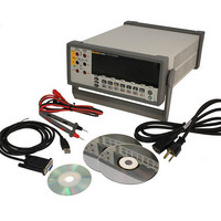
USB CABLE KIT SW DMM 5.5 RES
Manufacturer
Fluke Electronics
Type
Digital (DMM)r
Datasheet
1.8808A_120V.pdf
(100 pages)
Specifications of 8808A/SU 120V
Includes
Test Leads
Style
Bench
Display Digits
5.5
Display Type
VFD, Dual
Display Count
200000
Function
Voltage, Current, Resistance, Frequency
Functions, Extra
Continuity, dB, Diode Test
Features
Hold, Min/Max, RS-232 Port
Ranging
Auto/Manual
Response
True RMS
Lead Free Status / RoHS Status
Not applicable / RoHS non-compliant
Other names
614-1069


Table
1-1.
1-2.
1-3.
2-1.
2-2.
3-1.
3-2.
3-3.
3-4.
3-5.
3-6.
3-7.
3-8.
3-9.
4-1.
4-2.
4-3.
4-4.
4-5.
4-6.
4-7.
4-8.
4-9.
4-10. Function Modifier Commands and Queries ........................................................... 4-19
4-11. Range and Measurement Rate Commands and Queries ........................................ 4-21
4-12. Measurement Queries............................................................................................. 4-23
4-13. Compare Commands and Queries.......................................................................... 4-24
4-14. Trigger Configuration Commands ......................................................................... 4-24
4-15. Miscellaneous Commands and Queries ................................................................. 4-25
4-16. Measurement Units Output with Format 2............................................................. 4-25
4-17. Remote/Local Configuration Commands............................................................... 4-26
4-18. Save / Call System Configuration Commands ....................................................... 4-26
A-1. Allowable Combinations of Measurements ........................................................... A-2
A-2. Sample Dual Display Applications ........................................................................ A-3
A-3. Typical Measurement Intervals (in seconds) for Dual Display Measurements ..... A-6
Safety Information ................................................................................................. 1-5
Safety and Electrical Symbols................................................................................ 1-6
Accessories............................................................................................................. 1-7
Line Voltage to Fuse Rating................................................................................... 2-4
Line-Power Cord Types Available from Fluke...................................................... 2-7
Front-Panel Features .............................................................................................. 3-4
Display Annunciators and Indicators ..................................................................... 3-7
Rear-Panel Features ............................................................................................... 3-8
RS-232 Pin Out ...................................................................................................... 3-17
RS232 Pin Out........................................................................................................ 3-19
Second Level Operations ....................................................................................... 3-21
List Editor Options................................................................................................. 3-23
Number Editor Options .......................................................................................... 3-24
Factory Power-Up Configuration........................................................................... 3-25
RS-232 Communication Parameters Factory Settings ........................................... 4-4
Print Rates in RS-232 Print-Only Mode ................................................................ 4-5
Trigger Types ......................................................................................................... 4-9
RS-232 Reading Transfer Rates............................................................................. 4-10
Status Register Summary ....................................................................................... 4-11
Description of Bits in ESR and ESE ...................................................................... 4-14
Description of Bits in the Status Byte Register (STB)........................................... 4-14
Common Commands.............................................................................................. 4-16
Function Commands and Queries .......................................................................... 4-17
Title
v
List of Tables
Page