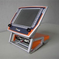
MEDIA5200KIT1 Freescale Semiconductor, MEDIA5200KIT1 Datasheet - Page 13

MEDIA5200KIT1
Manufacturer Part Number
MEDIA5200KIT1
Description
MCU, MPU & DSP Development Tools MEDIA5200 SW DEVT SYSTEM
Manufacturer
Freescale Semiconductor
Specifications of MEDIA5200KIT1
Processor To Be Evaluated
MPC5200B
Data Bus Width
32 bit
Interface Type
Ethernet, USB
Lead Free Status / Rohs Status
Not Compliant
- Current page: 13 of 72
- Download datasheet (979Kb)
1.3.2
Table 12
1.3.3
Freescale Semiconductor
1
2
•
•
CAUTION—The SYS_XTAL_IN frequency and system PLL_CFG[0–6] settings must be chosen such that the resulting
system frequencies do not exceed their respective maximum or minimum operating frequencies. See the MPC5200B
User’s Manual (MPC5200BUM).
SYS_XTAL_IN duty cycle is measured at V
t
t
CYCLE
t
t
CV
Sym
CV
Input conditions:
All Inputs: tr, tf <= 1 ns
Output Loading:
All Outputs: 50 pF
DUTY
provides the operating frequency information for the MPC5200B.
RISE
FALL
1
2
3
4
5
6
SYSCLK
IH
IL
AC Operating Frequency Data
Clock AC Specifications
PCI / Local Plus Bus Clock
SYS_XTAL_IN duty cycle (measured at V
e300 Processor Core
PLL Input Range
SDRAM Clock
XL Bus Clock
IP Bus Clock
V
M
SYS_XTAL_IN input voltage high
t
SYS_XTAL_IN input voltage low
DUTY
SYS_XTAL_IN cycle time.
Figure 2. Timing Diagram—SYS_XTAL_IN
SYS_XTAL_IN rise time.
SYS_XTAL_IN fall time.
t
CYCLE
Table 13. SYS_XTAL_IN Timing
Description
Table 12. Clock Frequencies
V
MPC5200B Data Sheet, Rev. 4
M
t
M
DUTY
.
V
M
(1)
15.6
Min
—
—
—
—
—
M
).
t
(2)
RISE
CV
CV
IH
IL
Max
400
133
133
133
66
35
28.6
40.0
Min
2.0
—
—
—
Max
64.1
60.0
5.0
5.0
0.8
—
Units
MHz
MHz
MHz
MHz
MHz
MHz
Units
ns
ns
ns
%
V
V
t
FALL
SpecID
SpecID
A2.1
A2.2
A2.3
A2.4
A2.5
A2.6
A1.1
A1.2
A1.3
A1.4
A1.5
A1.6
13
Related parts for MEDIA5200KIT1
Image
Part Number
Description
Manufacturer
Datasheet
Request
R

Part Number:
Description:
PRESENTER, MEDIA POINTER 100, GENIUS
Manufacturer:
GENIUS
Datasheet:

Part Number:
Description:
MEDIA CONVERTER, 3PORT, 2XRJ45-1XSC/ST
Manufacturer:
OPTO 22
Datasheet:

Part Number:
Description:
Media access controller for Ethernet (MACETM)
Manufacturer:
Advanced Micro Devices
Datasheet:

Part Number:
Description:
Media access controller for Ethernet (MACETM)
Manufacturer:
Advanced Micro Devices
Datasheet:

Part Number:
Description:
†Media Converter 400MHz CPU, EPON/GPON/P2P, 10/100/1000Base-T + SGMII +2xTD
Manufacturer:
Marvell

Part Number:
Description:
MEDIA MOD 2 X TWISTED-PAIR PORTS
Manufacturer:
Phoenix Contact
Datasheet:

Part Number:
Description:
MEDIA MOD 2 X TWISTED-PAIR PORTS
Manufacturer:
Phoenix Contact
Datasheet:

Part Number:
Description:
MEDIA MOD 2 X TWISTED-PAIR PORTS
Manufacturer:
Phoenix Contact
Datasheet:

Part Number:
Description:
MEDIA MOD 100BASE-FX MULTIMODE
Manufacturer:
Phoenix Contact
Datasheet:
Part Number:
Description:
Manufacturer:
Freescale Semiconductor, Inc
Datasheet:
Part Number:
Description:
Manufacturer:
Freescale Semiconductor, Inc
Datasheet:
Part Number:
Description:
Manufacturer:
Freescale Semiconductor, Inc
Datasheet:
Part Number:
Description:
Manufacturer:
Freescale Semiconductor, Inc
Datasheet:
Part Number:
Description:
Manufacturer:
Freescale Semiconductor, Inc
Datasheet:


