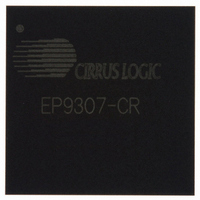
EP9307-CR Cirrus Logic Inc, EP9307-CR Datasheet - Page 778

EP9307-CR
Manufacturer Part Number
EP9307-CR
Description
IC,MICROPROCESSOR,32-BIT,CMOS,BGA,272PIN,PLASTIC
Manufacturer
Cirrus Logic Inc
Series
EP9r
Specifications of EP9307-CR
Rohs Compliant
NO
Core Processor
ARM9
Core Size
16/32-Bit
Speed
200MHz
Connectivity
EBI/EMI, Ethernet, I²C, IrDA, Keypad/Touchscreen, SPI, UART/USART, USB
Peripherals
AC'97, DMA, I²:S, LCD, LED, MaverickKey, POR, PWM, WDT
Number Of I /o
14
Program Memory Type
ROMless
Ram Size
32K x 8
Voltage - Supply (vcc/vdd)
1.65 V ~ 3.6 V
Data Converters
A/D 8x12b
Oscillator Type
External
Operating Temperature
0°C ~ 70°C
Package / Case
272-TFBGA
Processor Series
EP93xx
Core
ARM920T
Data Bus Width
32 bit
3rd Party Development Tools
MDK-ARM, RL-ARM, ULINK2
Development Tools By Supplier
EDB9307A-Z
Lead Free Status / RoHS Status
Contains lead / RoHS non-compliant
For Use With
598-1133 - KIT DEVELOPMENT EP9307 ARM9
Eeprom Size
-
Program Memory Size
-
Lead Free Status / Rohs Status
No
Other names
598-1254
Available stocks
Company
Part Number
Manufacturer
Quantity
Price
Company:
Part Number:
EP9307-CR
Manufacturer:
CIRRUSL
Quantity:
5
Part Number:
EP9307-CRZ
Manufacturer:
CIRRUS
Quantity:
20 000
Part Number:
EP9307-CRZ/E2
Manufacturer:
CIRRUS
Quantity:
20 000
Company:
Part Number:
EP9307-CRZR
Manufacturer:
Cirrus Logic Inc
Quantity:
10 000
- Current page: 778 of 824
- Download datasheet (13Mb)
27
27-8
27.2.7.3.1 General Note
27.2.7.3.2 Multi-word DMA
IDE Interface
EP93xx User’s Guide
27.2.7.3 IDE DMA Programming Considerations
This is a general guideline for programming the DMA controller to properly interact with the
IDE controller without receiving malformed data. All cases assume the DMA controller is
capable of burst read or burst write operations. Non-ideal DMA controllers may be able to
avoid wait-states due to less than optimal bus utilization.
Please verify that the DMA controller will ignore DMA requests if it's transfer counter register
has gone to zero. If this is not the case, the DMA controller must be configured to time out
based on the wait-state table in
allowed.
Follow the wait-state number listed in the wait-state table in
word bursts are not allowed.
Note: This is the number of wait states required by the IDE Controller to deassert the DMA
Multi-word DMA Read from IDE Controller:
Controller request line after each word transfer is complete.
Wait States:
Multi-word DMA Write to IDE Controller:
Ultra DMA Read from IDE Controller:
Read
Write
Ultra DMA Write to IDE Controller:
Table 27-3. Wait State Value for the DMA M2M Register Control.PWSC
Operation
Table 27-4. HCLK Cycles to De-assert DMA Request
Multi-Word DMA Request
Copyright 2007 Cirrus Logic
Table 27-3
0
3
HCLK Cycle
0
1
0
1
0
1
2
3
0
1
2
and
Table
AHB write command
DMAide deasserts
AHB read command
AHB read data, DMAide deasserts
AHB write command
Data stored in IDE register
Data stored in FIFO, FIFO status updates
DMAide deasserts
AHB read command
AHB read data, word counter updates
DMAide deasserts
27-4. Quad-word bursts are not
Table 27-3
Ultra DMA Request
Event
1
2
and
Table
27-4. Quad-
DS785UM1
Related parts for EP9307-CR
Image
Part Number
Description
Manufacturer
Datasheet
Request
R

Part Number:
Description:
IC ARM9 SOC ARM920T 272TFBGA
Manufacturer:
Cirrus Logic Inc
Datasheet:

Part Number:
Description:
IC ARM9 SOC ARM920T 272TFBGA
Manufacturer:
Cirrus Logic Inc
Datasheet:

Part Number:
Description:
IC Universal Platform ARM9 SOC Prcessor
Manufacturer:
Cirrus Logic Inc
Datasheet:

Part Number:
Description:
IC Universal Platform ARM9 SOC Prcessor
Manufacturer:
Cirrus Logic Inc

Part Number:
Description:
IC Universal Platform ARM9 SOC Prcessor
Manufacturer:
Cirrus Logic Inc
Datasheet:

Part Number:
Description:
Microcontrollers (MCU) IC Universal Platfrm ARM9 SOC Prcessor
Manufacturer:
Cirrus Logic Inc

Part Number:
Description:
Microcontrollers (MCU) IC Universal Platfrm ARM9 SOC Prcessor
Manufacturer:
Cirrus Logic Inc

Part Number:
Description:
MCU, MPU & DSP Development Tools Eval Bd Uni. ARM9 SOC Processor
Manufacturer:
Cirrus Logic Inc
Datasheet:

Part Number:
Description:
Development Kit
Manufacturer:
Cirrus Logic Inc
Datasheet:

Part Number:
Description:
Development Kit
Manufacturer:
Cirrus Logic Inc
Datasheet:

Part Number:
Description:
High-efficiency PFC + Fluorescent Lamp Driver Reference Design
Manufacturer:
Cirrus Logic Inc
Datasheet:

Part Number:
Description:
Development Kit
Manufacturer:
Cirrus Logic Inc
Datasheet:

Part Number:
Description:
Ref Bd For Speakerbar MSA & DSP Products
Manufacturer:
Cirrus Logic Inc


