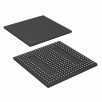
ADSP-BF538BBCZ-5F4 Analog Devices Inc, ADSP-BF538BBCZ-5F4 Datasheet - Page 22

ADSP-BF538BBCZ-5F4
Manufacturer Part Number
ADSP-BF538BBCZ-5F4
Description
IC, FLOAT-PT DSP, 16BIT, 533MHZ, BGA-316
Manufacturer
Analog Devices Inc
Series
Blackfinr
Type
Fixed Pointr
Specifications of ADSP-BF538BBCZ-5F4
No. Of Bits
16 Bit
Frequency
533MHz
Supply Voltage
1.25V
Embedded Interface Type
CAN, I2C, PPI, SPI, TWI, UART
No. Of I/o's
54
Flash Memory Size
512KB
Interface
CAN, SPI, SSP, TWI, UART
Clock Rate
533MHz
Non-volatile Memory
FLASH (512 kB)
On-chip Ram
148kB
Voltage - I/o
3.00V, 3.30V
Voltage - Core
1.25V
Operating Temperature
-40°C ~ 85°C
Mounting Type
Surface Mount
Package / Case
316-CSPBGA
Lead Free Status / RoHS Status
Lead free / RoHS Compliant
For Use With
ADZS-BFAUDIO-EZEXT - BOARD EVAL AUDIO BLACKFIN
Lead Free Status / RoHS Status
Lead free / RoHS Compliant, Lead free / RoHS Compliant
ADSP-BF538/ADSP-BF538F
Table 10. Pin Descriptions (Continued)
1
2
Pin Name
PF7/PPI12/SPI0SEL7
PF8/PPI11
PF9/PPI10
PF10/PPI9
PF11/PPI8
PF12/PPI7
PF13/PPI6
PF14/PPI5
PF15/PPI4
Real-Time Clock
RTXI
RTXO
JTAG Port
TCK
TDO
TDI
TMS
TRST
EMU
Clock
CLKIN
XTAL
Mode Controls
RESET
NMI
BMODE1–0
Voltage Regulator
VROUT1–0
GPW
Supplies
V
V
V
GND
Refer to
This pin is 5 V-tolerant when configured as an input and an open-drain when configured as an output; therefore, only the VOL curves in
on Page 47
DDEXT
DDINT
DDRTC
Figure 32 on Page 46
and the Fall Time curves in
to
Figure 42 on Page
Figure 49 on Page 50
I
I
I/O
I/O
I/O
I/O
I/O
I/O
I/O
I/O
I/O
I/O
O
I
O
I
I
I
O
O
I
I
I
O
I 5 V
P
P
P
G
48.
Function
GPIO/PPI12/SPI0 Slave Select Enable 7
GPIO/PPI11
GPIO/PPI10
GPIO/PPI9
GPIO/PPI8
GPIO/PPI7
GPIO/PPI6
GPIO/PPI5
GPIO/PPI4
RTC Crystal Input (This pin should be pulled low when not used.)
RTC Crystal Output (Does not three-state in hibernate.)
JTAG Clock
JTAG Serial Data Out
JTAG Serial Data In
JTAG Mode Select
JTAG Reset (This pin should be pulled low if the JTAG port will not be used.)
Emulation Output
Clock/Crystal Input
Crystal Output
Reset
Nonmaskable Interrupt (This pin should be pulled high when not used.)
Boot Mode Strap (These pins must be pulled to the state required for the
desired boot mode.)
External FET Drive 0 (These pins should be left unconnected when
not used and are driven high during hibernate.)
General-Purpose Regulator Wake-Up (This pin should be pulled high
when not used.)
I/O Power Supply
Internal Power Supply
Real-Time Clock Power Supply (This pin should be connected to V
when not used and should remain powered at all times.)
Ground
and
Rev. D | Page 22 of 56 | July 2010
Figure 50 on Page 50
apply when configured as an output.
Figure 36 on Page 47
DDEXT
Driver Type
C
C
C
C
C
C
C
C
C
C
C
and
Figure 37
1


