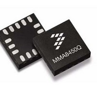
MMA8450QT Freescale Semiconductor, MMA8450QT Datasheet - Page 27

MMA8450QT
Manufacturer Part Number
MMA8450QT
Description
Board Mount Accelerometers 12bit 3-Axis FIFO HPF PL
Manufacturer
Freescale Semiconductor
Specifications of MMA8450QT
Sensing Axis
X, Y, Z
Acceleration
2 g, 4 g, 8 g
Digital Output - Number Of Bits
12 bit
Supply Voltage (max)
1.89 V
Supply Voltage (min)
1.71 V
Supply Current
3 uA
Maximum Operating Temperature
+ 85 C
Minimum Operating Temperature
- 40 C
Shutdown
Yes
Sensitivity
0.976 mg/digit, 1.953 mg/digit, 3.906 mg/digit
Package / Case
QFN-16
Output Type
Digital
Package Type
QFN
Operating Temperature (min)
-40C
Operating Temperature (max)
85C
Operating Temperature Classification
Industrial
Product Depth (mm)
3mm
Product Height (mm)
1mm
Product Length (mm)
3mm
Mounting
Surface Mount
Pin Count
16
Acceleration Range
± 2g, ± 4g, ± 8g
No. Of Axes
3
Ic Interface Type
I2C, Serial
Sensor Case Style
QFN
No. Of Pins
16
Supply Voltage Range
1.71V To 1.89V
Rohs Compliant
Yes
Lead Free Status / RoHS Status
Lead free / RoHS Compliant
Available stocks
Company
Part Number
Manufacturer
Quantity
Price
Company:
Part Number:
MMA8450QT
Manufacturer:
RALINK
Quantity:
2 940
Part Number:
MMA8450QT
Manufacturer:
FREESCALE
Quantity:
20 000
0x15: INT_SOURCE System Interrupt Status Register
indicate which function has asserted an interrupt and conversely the bits that are cleared (logic ‘0’) indicate which function has
not asserted or has de-asserted an interrupt. The interrupts are rising edge sensitive. The bits are set by a low to high transition
and are cleared by reading the appropriate interrupt source register.
0x15 INT_SOURCE: System Interrupt Status Register (Read Only)
Table 17. INT_SOURCE Description
Sensors
Freescale Semiconductor
SRC_ASLP
In the interrupt source register the status of the various embedded features can be determined.The bits that are set (logic ‘1’)
SRC_FF_MT_1
SRC_FF_MT_2
SRC_LNDPRT
INT_SOURCE
SRC_TRANS
SRC_PULSE
SRC_DRDY
SRC_ASLP
Bit 7
SRC_FIFO
SRC_FIFO
Bit 6
Auto-Sleep/Wake interrupt status bit
Logic ‘1’ indicates that an interrupt event that can cause a “Wake-to-Sleep” or “Sleep-to-Wake” system mode transition
has occurred.
Logic ‘0’ indicates that no “Wake-to-Sleep” or “Sleep-to-Wake” system mode transition interrupt event has occurred.
“Wake-to-Sleep” transition occurs when no interrupt occurs for a time period that exceeds the user specified limit
(ASLP_COUNT). This causes the system to transition to a user specified low ODR setting.
“Sleep-to-Wake” transition occurs when the user specified interrupt event has woken the system; thus causing the
system to transition to a user specified high ODR setting.
Reading the SYSMOD register clears the SRC_ASLP bit.
FIFO interrupt status bit
Logic ‘1’ indicates that a FIFO interrupt event such as an overflow event or watermark has occurred. Logic ‘0’ indicates
that no FIFO interrupt event has occurred.
FIFO interrupt event generators: FIFO Overflow, or (Watermark: F_CNT = F_WMRK) and the interrupt has been
enabled.
This bit is cleared by reading the F_STATUS register.
Transient interrupt status bit
indicates that no transient event has occurred.
This bit is asserted whenever “EA” bit in the TRANS_SRC is asserted and the interrupt has been enabled.
This bit is cleared by reading the TRANS_SRC register.
Landscape/Portrait Orientation interrupt status bit
Logic ‘1’ indicates that an interrupt was generated due to a change in the device orientation status. Logic ‘0’ indicates
that no change in orientation status was detected.
This bit is asserted whenever “NEWLP” bit in the PL_STATUS is asserted and the interrupt has been enabled.
This bit is cleared by reading the PL_STATUS register.
Pulse interrupt status bit
Logic ‘1’ indicates that an interrupt was generated due to single and/or double pulse event. Logic ‘0’ indicates that no
pulse event was detected.
This bit is asserted whenever “EA” bit in the PULSE_SRC is asserted and the interrupt has been enabled.
This bit is cleared by reading the PULSE_SRC register.
Freefall/Motion1 interrupt status bit
Logic ‘1’ indicates that the Freefall/Motion1 function interrupt is active.
Logic ‘0’ indicates that no Freefall or Motion event was detected.
This bit is asserted whenever “EA” bit in the FF_MT_SRC_1 register is asserted and the FF_MT interrupt has been
enabled.
This bit is cleared by reading the FF_MT_SRC_1 register.
Freefall/Motion2 interrupt status bit
Logic ‘1’ indicates that the Freefall/Motion2 function interrupt is active.
Logic ‘0’ indicates that no Freefall or Motion event was detected.
This bit is asserted whenever “EA” bit in the FF_MT_SRC_2 register is asserted and the FF_MT interrupt has been
enabled.
This bit is cleared by reading the FF_MT_SRC_2 register.
Data Ready interrupt bit status
Logic ‘1’ indicates that the X,Y,Z data ready interrupt is active indicating the presence of new data and/or data overrun.
Otherwise if it is a logic ‘0’ the X,Y,Z interrupt is not active.
This bit is asserted when the ZYXOW and/or ZYXDR is set and the interrupt has been enabled.
This bit is cleared by reading the STATUS and X, Y, or Z register.
Logic ‘1’ indicates that an acceleration transient value greater than user specified threshold has occurred. Logic ‘0’
SRC_TRANS
Bit 5
SRC_LNDPRT
Bit 4
SRC_PULSE
Description
Bit 3
SRC_FF_MT_1 SRC_FF_MT_2
Bit 2
Bit 1
SRC_DRDY
MMA8450Q
Bit 0
27


