XBP09-DPSIT-156 Digi International, XBP09-DPSIT-156 Datasheet - Page 20
XBP09-DPSIT-156
Manufacturer Part Number
XBP09-DPSIT-156
Description
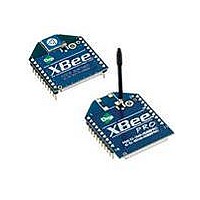
MODULE XBEE PRO W/RPSMA
Manufacturer
Digi International
Series
XBEE-PRO™r
Specifications of XBP09-DPSIT-156
Frequency
902MHz ~ 928MHz
Data Rate - Maximum
156kbps
Modulation Or Protocol
FHSS
Applications
ISM
Power - Output
17dBm (50mW)
Sensitivity
-100dBm
Voltage - Supply
3 V ~ 3.6 V
Current - Receiving
80mA
Current - Transmitting
210mA
Data Interface
PCB, Through Hole
Antenna Connector
RP-SMA
Operating Temperature
-40°C ~ 85°C
Package / Case
Module
Lead Free Status / RoHS Status
Lead free / RoHS Compliant
Memory Size
-
Lead Free Status / Rohs Status
Lead free / RoHS Compliant
Other names
602-1169


XBee‐PRO® 900 RF Modules
Commissioning Pushbutton
Associate LED
The commissioning pushbutton definitions provide a variety of simple functions to aid in deploying
devices in a network. The commissioning button functionality on pin 20 is enabled by setting the
D0 command to 1 (enabled by default).
Button presses may be simulated in software using the ATCB command. ATCB should be issued
with a parameter set to the number of button presses to execute. (i.e. sending ATCB1 will execute
the action(s) associated with a single button press.)
The node identification frame is similar to the node discovery response frame – it contains the
device’s address, node identifier string (NI command), and other relevant data. All API devices
that receive the node identification frame send it out their UART as an API Node Identification
Indicator frame (0x95).
The Associate pin (pin 15) can provide indication of the device's sleep status and diagnostic
information. To take advantage of these indications, an LED can be connected to the Associate pin
as shown in the figure above. The Associate LED functionality is enabled by setting the D5
command to 1 (enabled by default). If enabled, the Associate pin is configured as an output and
will behave as described in the following sections.
The Associate pin indicates the synchronization status of a sleep compatible node. On a non-sleep
compatible node the pin functions has a power indicator. The following table describes this
functionality:
The LT command can be used to override the blink rate of the Associate pin. When set to 0, the
device uses the default blink time (500ms for sleep coordinator, 250ms otherwise).
Button Presses
1
1
2
2
4
No
Yes
© 2009 Digi International, Inc.
compatible?
Sleep
Not configured for sleep
Configured for sleep
Not configured for sleep
Configured for sleep
Either
On, blinking green
On, solid green
Configuration and
Sync Status
LED Status
Sleep
Immediately sends a Node Identification
broadcast transmission.
All devices that receive this transmission will
blink their Associate LED rapidly for 1 second.
All API devices that receive this transmission
will send a Node Identification frame out their
UART (API ID 0x95)
Wakes the module for 30 seconds (or until the
entire network goes to sleep). Queues a Node
Identification broadcast transmission to be sent
at the beginning of the next network wake cycle.
All devices that receive this transmission will
blink their Associate LED rapidly for 1 second.
All API devices that receive this transmission
will send a Node Identification frame out their
UART (API ID 0x95).
Not supported.
Causes a node which is configured with
sleeping router nomination enabled (see
description of the ATSO – sleep options
command in the XBee module’s Product
Manual) to immediately nominate itself as the
network sleep coordinator.
Issues an ATRE to restore module parameters
to default values.
The device is powered and operating properly.
The device has not synchronized with the
network or has lost synchronization with the
network.
Meaning
Action
20
Related parts for XBP09-DPSIT-156
Image
Part Number
Description
Manufacturer
Datasheet
Request
R

Part Number:
Description:
KIT STARTER XBEE PRO 900MHZ
Manufacturer:
Digi International
Datasheet:
Part Number:
Description:
XBEE-PROMESH 900 RANGE
Manufacturer:
Digi International
Datasheet:
Part Number:
Description:
XBEE-PRO XSC -100MW 9.6KBPS
Manufacturer:
Digi International
Datasheet:
Part Number:
Description:
KIT STARTER PROMESH XBEE PRO
Manufacturer:
Digi International
Datasheet:
Part Number:
Description:
MODULE XBEE PRO W/WIRE ANT
Manufacturer:
Digi International
Datasheet:
Part Number:
Description:
MODULE XBEE PRO W/U.FL
Manufacturer:
Digi International
Datasheet:

Part Number:
Description:
Zigbee / 802.15.4 Modules & Development Tools XBee-PRO DigiMesh900 900MHz50mW RPSMA ANT
Manufacturer:
Digi International
Datasheet:
Part Number:
Description:
Zigbee / 802.15.4 Modules & Development Tools XBeePRO DigiMesh 900 50mW,w/ant,156000bps
Manufacturer:
Digi International
Datasheet:
Part Number:
Description:
Zigbee / 802.15.4 Modules & Development Tools XBee-PRO XSC 900 MHz 100mW,w/ant,9600 bps
Manufacturer:
Digi International
Datasheet:
Part Number:
Description:
Zigbee / 802.15.4 Modules & Development Tools XBee-PRO XSC 900MHz 100mW RPSMA 9600bps
Manufacturer:
Digi International
Datasheet:
Part Number:
Description:
IC ARM MICROPROCESSOR 177BGA
Manufacturer:
Digi International
Datasheet:
Part Number:
Description:
DIGI CONNECT 4MB FLASH 8MB RAM
Manufacturer:
Digi International
Datasheet:

Part Number:
Description:
ME 8MB SDRAM 2MB FLASH SINGLE
Manufacturer:
Digi International
Datasheet:
Part Number:
Description:
ME 8MB SDRAM 2MB FLASH SINGLE
Manufacturer:
Digi International
Datasheet:

Part Number:
Description:
MODULE 9P 8MB SDRAM 4MB FLASH
Manufacturer:
Digi International/Maxstream
Datasheet: