XBP09-DPSIT-156 Digi International, XBP09-DPSIT-156 Datasheet
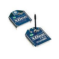
XBP09-DPSIT-156
Specifications of XBP09-DPSIT-156


Related parts for XBP09-DPSIT-156


XBP09-DPSIT-156 Summary of contents
Page 1
... XBee-PRO® 900/DigiMesh™ 900 RF Modules XBee-PRO® 900 RF Modules RF Module Operation RF Module Configuration Appendices RF Modules by Digi International Firmware version: 8x4x XBee-PRO DigiMesh 900 28x4x XBee-PRO DigiMesh 900 (International variant) 1x4x XBee-PRO 900 2104x XBee-PRO 900 (International variant) Digi International Inc. ...
Page 2
... XBee‐PRO® 900 RF Modules © 2009 Digi International, Inc. All rights reserved No part of the contents of this manual may be transmitted or reproduced in any form or by any means without the written permission of Digi International, Inc. ...
Page 3
XBee‐PRO® 900 RF Modules Contents 1. XBee-PRO® 900 RF Modules 4 Key Features 4 Worldwide Acceptance 4 Specifications 5 Mechanical Drawings 6 Mounting Considerations 6 Pin Signals 7 Design Notes 8 Power Supply Design 8 Recommended Pin Connections 8 Board Layout 8 Electrical ...
Page 4
The XBee-PRO® 900 RF Modules were engineered to support the unique needs of low-cost, low- power wireless sensor networks. The modules require minimal power and provide reliable delivery of data between remote devices. The modules operate within the ISM ...
Page 5
XBee‐PRO® 900 RF Modules Specifications Specifications of the XBee‐PRO® 900 RF Module Specification Performance Indoor/Urban Range Outdoor RF line-of-sight Range Transmit Power Output RF Data Rate Data Throughput Serial Interface Data Rate (software selectable) Receiver Sensitivity Power Requirements Supply Voltage Transmit Current Idle / Receive Current Sleep Current General ...
Page 6
XBee‐PRO® 900 RF Modules Mechanical Drawings Mechanical drawings of the XBee‐PRO® 900 RF Modules (antenna opstions not shown) . Mechanical Drawings for the RPSMA Variant Mounting Considerations The XBee-PRO® 900 RF Module (through-hole) was designed to mount into a receptacle (socket) and therefore does not require any soldering when mounting board. The Development Kits contain RS-232 ...
Page 7
XBee‐PRO® 900 RF Modules XBee‐PRO® 900 Module Mounting to an RS‐232 Interface Board. The receptacles used on Digi development boards are manufactured by Century Interconnect. Several other manufacturers provide comparable mounting solutions; however, Digi currently uses the following receptacles: • Through-hole single-row receptacles - Samtec P/N: MMS-110-01-L-SV (or equivalent) • Surface-mount ...
Page 8
XBee‐PRO® 900 RF Modules Pin Assignments for the XBee‐PRO® 900 Modules Pin # Name 18 AD2 / DIO2 19 AD1 / DIO1 AD0 / DIO0 / Commissioning 20 Button Design Notes The XBee modules do not specifically require any external circuitry or specific connections for proper operation. However, there ...
Page 9
XBee‐PRO® 900 RF Modules Electrical Characteristics DC Characteristics of the XBee‐PRO® 900 (VCC =3.0‐3.6VDC) Symbol Parameter V Input Low Voltage IL V Input High Voltage IH V Output Low Voltage OL V Output High Voltage OH II Input Leakage Current IN © 2009 Digi International, Inc. Condition Min All Digital Inputs - All Digital ...
Page 10
Serial Communications The XBee-PRO® RF Modules interface to a host device through a logic-level asynchronous serial port. Through its serial port, the module can communicate with any logic and voltage compatible UART; or through a level translator to any ...
Page 11
XBee‐PRO® 900 RF Modules Internal Data Flow Diagram Serial DIN Receiver Buffer CTS Processor VCC GND Serial Transmit DOUT Buffer RTS Serial Receive Buffer When serial data enters the RF module through the DIN Pin (pin 3), the data is stored in the serial receive buffer ...
Page 12
XBee‐PRO® 900 RF Modules RTS Flow Control If RTS flow control is enabled (D6 command), data in the serial transmit buffer will not be sent out the DOUT pin as long as RTS is de-asserted (set high). The host device should not de-assert ...
Page 13
XBee‐PRO® 900 RF Modules A Comparison of Transparent and API Operation The following table compares the advantages of transparent and API modes of operation: Simple Interface Easy to support Easy to manage data transmissions to multiple destinations Received data frames indicate the sender's ...
Page 14
XBee‐PRO® 900 RF Modules Transmit Mode Sequence Idle Mode New Transmission Data Discarded When data is transmitted from one node to another, a network-level acknowledgement is transmitted back across the established route to the source node. This acknowledgement packet indicates to the source node that ...
Page 15
XBee‐PRO® 900 RF Modules • Input three plus characters (“+++”) within one second [CC (Command Sequence Character) parameter = 0x2B.] • No characters sent for one second [GT (Guard Times) parameter = 0x3E8] Once the AT command mode sequence has been issued, the ...
Page 16
XBee‐PRO® 900 RF Modules Sleep Mode Sleep mode allows the RF module to enter a low power state. The XBee DigiMesh 900 modules support a network synchronized sleep to conserve power.. © 2009 Digi International, Inc. 16 ...
Page 17
Remote Configuration Commands A module in API mode has provisions to send configuration commands to remote devices using the Remote Command Request API frame (See API Operations chapter.) This API frame can be used to send commands to a ...
Page 18
XBee‐PRO® 900 RF Modules Device Placement For a mesh network installation to be successful, the installer must be able to determine where to place individual XBee devices to establish reliable links throughout the mesh network. Link Testing A good way to measure the ...
Page 19
XBee‐PRO® 900 RF Modules The DB value can be determined in hardware using the RSSI/PWM module pin (pin 6). If the RSSI PWM functionality is enabled (P0 command), when the module receives data, the RSSI PWM is set to a value based on ...
Page 20
XBee‐PRO® 900 RF Modules Commissioning Pushbutton The commissioning pushbutton definitions provide a variety of simple functions to aid in deploying devices in a network. The commissioning button functionality on pin 20 is enabled by setting the D0 command to 1 (enabled by default). ...
Page 21
XBee‐PRO® 900 RF Modules Sleep compatible? Yes Yes Diagnostics Support The Associate pin works with the commissioning pushbutton to provide additional diagnostics behaviors to aid in deploying and testing a network. If the commissioning push button is pressed once the device transmits a ...
Page 22
XBee‐PRO® 900 RF Modules Module Pin Names AD0 / DIO0 / CommissioningButton See the command table for more information. Pullup resistors for each digital input can be enabled using the PR command. 1 Sample Sets 2 Digital Channel Mask 1 Analog Channel Mask ...
Page 23
XBee‐PRO® 900 RF Modules Example 0x0124\r Periodic I/O Sampling Periodic sampling allows an XBee-PRO 900 module to take an IO sample and transmit remote device at a periodic rate. The periodic sample rate is set by the IR command. If ...
Page 24
DigiMesh Networking Mesh networking allows messages to be routed through several different nodes to a final destination. DigiMesh firmware allows system integrators to bolster their networks with the self- healing attributes of mesh networking. In the event that one ...
Page 25
XBee‐PRO® 900 RF Modules Data Transmission and Routing Unicast Addressing When transmitting while using Unicast communications, reliable delivery of data is accomplished using retries and acknowledgements. The number of retries is determined by the MR (Network Retries) parameter. RF data packets are sent ...
Page 26
XBee‐PRO® 900 RF Modules Throughput Throughput in a DigiMesh network can vary by a number of variables, including: number of hops, encryption enabled/disabled, sleeping end devices, failures/route discoveries. Our empirical testing showed the following throughput performance in a robust operating environment (low interference). ...
Page 27
XBee‐PRO® 900 RF Modules BroadcastTxTime=NN*NH*(MT+1)* 18mSec Transmitting a unicast with a known route When a route to a destination node is known the transmission time is largely a function of the number of hops and retries. The timeout associated with a unicast assumes ...
Page 28
XBee‐PRO® 900 RF Modules Cyclic Sleep Mode (SM=8) A node in cyclic sleep mode sleeps for a programmed time, wakes in unison with other nodes, exchanges data and sync messages, and then returns to sleep. While asleep, it cannot receive RF messages or ...
Page 29
XBee‐PRO® 900 RF Modules the sync will be rejected and a corrective sync will be sent to the sleep coordinator. Deployment mode can be disabled using the sleep options command (SO). A sleep coordinator which is not in deployment mode or which has ...
Page 30
XBee‐PRO® 900 RF Modules Becoming a Sleep Coordinator A node can become a sleep coordinator in one of four ways: Preferred Sleep Coordinator Option A node can be specified to always act as a sleep coordinator. This is done by setting the preferredsleep ...
Page 31
XBee‐PRO® 900 RF Modules Note #1: For normal operations a module will use the sleep and wake parameters it gets from the sleep sync message, not the ones specified in its SP and ST parameters. The SP and ST parameters are not updated ...
Page 32
XBee‐PRO® 900 RF Modules Starting a Sleeping Network By default, all new nodes operate in normal (non-sleep) mode. To start a sleeping network, follow these steps: 1. Enable the preferred sleep coordinator option on one of the nodes and set its SM to ...
Page 33
XBee‐PRO® 900 RF Modules Changing Sleep Parameters Changes to the sleep and wake cycle of the network can be made by selecting any node in the network and changing the SP and/ the node to values different than those that the ...
Page 34
XBee‐PRO® 900 RF Modules • If multiple modules in the network have had the non-sleep coordinator sleep option bit dis- abled and are thus eligible to be nominated as a sleep coordinator. • If the modules in the network are not using the ...
Page 35
Special Special Commands AT Name and Description Command Write. Write parameter values to non-volatile memory so that parameter modifications persist through subsequent resets. WR Note: Once WR is issued, no additional characters should be sent to the module until after ...
Page 36
XBee‐PRO® 900 RF Modules Serial Interfacing (I/O) Serial Interfacing Commands AT Name and Description Command API mode. Set or read the API mode of the radio. The following settings are allowed: 0 API mode is off. All UART input and output is raw data and ...
Page 37
XBee‐PRO® 900 RF Modules I/O Commands AT Name and Description Command DIO11/PWM1 Configuration. Configure options for the DIO11/PWM1 line of the module. Options include Input, unmonitored 2 = PWM1 Digital input, monitored 4 = Digital output low 5 = ...
Page 38
XBee‐PRO® 900 RF Modules I/O Commands AT Name and Description Command DIO8 Configuration. Configure options for the DIO8 line of the module. Options include Input, unmonitored Digital input, monitored 4 = Digital output low 5 = Digital output high ...
Page 39
XBee‐PRO® 900 RF Modules I/O Commands AT Name and Description Command IO Digital Change Detection. Set/Read the digital IO pins to monitor for changes in the IO state. IC works with the individual pin configuration commands (D0-D9, P0-P2 pin is enabled as ...
Page 40
XBee‐PRO® 900 RF Modules Diagnostics Diagnostics Commands AT Name and Description Command VR Firmware Version. Read firmware version of the module. HV Hardware Version. Read hardware version of the module. Configuration Code. Read the configuration code associated with the current AT CK command configuration.The ...
Page 41
XBee‐PRO® 900 RF Modules AT Command Options AT Command Options Commands AT Name and Description Command Command Mode Timeout. Set/Read the period of inactivity (no valid commands CT received) after which the RF module automatically exits AT Command Mode and returns to Idle Mode. CN Exit ...
Page 42
XBee‐PRO® 900 RF Modules Node Identification Commands AT Name and Description Command Network Discovery Options. Set/Read the options value for the network discovery command. The options bitfield value can change the behavior of the ND (network discovery) command and/or change what optional values are returned ...
Page 43
XBee‐PRO® 900 RF Modules AT Name and Description Command Sleep Options. Options Include: bit 0 = Preferred Sleep Coordinator bit 1 = Non-Sleep Coordinator SO bit 2 = Enable API sleep status messages bit 3 = Disable automatic early wakeup for missed syncs ...
Page 44
As an alternative to Transparent Operation, API (Application Programming Interface) Operations are available. API operation requires that communication with the module be done through a structured interface (data is communicated in frames in a defined order). The API specifies ...
Page 45
XBee‐PRO® 900 RF Modules Data bytes that need to be escaped: • 0x7E – Frame Delimiter • 0x7D – Escape • 0x11 – XON • 0x13 – XOFF Example - Raw UART Data Frame (before escaping interfering bytes): 0x7E 0x00 0x02 0x23 0x11 ...
Page 46
XBee‐PRO® 900 RF Modules Checksum To test data integrity, a checksum is calculated and verified on non-escaped data. To calculate: Not including frame delimiters and length, add all bytes keeping only the lowest 8 bits of the result and subtract the result from ...
Page 47
XBee‐PRO® 900 RF Modules Supporting the API Applications that support the API should make provisions to deal with new API frames that may be introduced in future releases. For example, a section of code on a host microprocessor that handles received serial API ...
Page 48
XBee‐PRO® 900 RF Modules Start Delimiter Length Frame-specific Data Checksum The above example illustrates an AT command when querying an NH value. AT Command - Queue Parameter Value Frame Type: 0x09 This API type ...
Page 49
XBee‐PRO® 900 RF Modules Start Delimiter Length Frame-specific Data Checksum Example: The example above shows how to send a transmission to a module where escaping is disabled (AP=1) with destination address 0x0013A200 40014011, payload ...
Page 50
XBee‐PRO® 900 RF Modules The broadcast radius can be set from 0xFF. If the broadcast radius exceeds the value of NH then the value of NH will be used as the radius. This parameter is only used for ...
Page 51
XBee‐PRO® 900 RF Modules Remote AT Command Request Frame Type: 0x17 Used to query or set module parameters on a remote device. For parameter changes on the remote device to take effect, changes must be applied, either by setting the apply changes options ...
Page 52
XBee‐PRO® 900 RF Modules AT Command Response Frame Type: 0x88 In response Command message, the module will send an AT Command Response message. Some commands will send back multiple frames (for example, the ND (Node Discover) command). Start Delimiter Length ...
Page 53
XBee‐PRO® 900 RF Modules Transmit Status Frame Type: 0x8B When a TX Request is completed, the module sends a TX Status message. This message will indicate if the packet was transmitted successfully or if there was a failure. Start Delimiter Length A P ...
Page 54
XBee‐PRO® 900 RF Modules Receive Packet Frame Type: (0x90) When the module receives an RF packet sent out the UART using this message type. Start Delimiter Length Frame-specific Data Checksum Example: In ...
Page 55
XBee‐PRO® 900 RF Modules Explicit Rx Indicator Frame Type:0x91 When the modem receives an RF packet it is sent out the UART using this message type (when AO=1). Frame Fields Start Delimiter Length Frame-specific Data k e ...
Page 56
XBee‐PRO® 900 RF Modules Remote Command Response Frame Type: 0x97 If a module receives a remote command response RF data frame in response to a Remote AT Command Request, the module will send a Remote AT Command Response message out the UART. Some ...
Page 57
Appendix A: Definitions Definitions Terms and Definitions PAN Network Address Route Request Route Reply Route Discovery DigiMesh Protocol Election Hopping Network Identifier Network Address Nomination Route Request Route Reply Route Discovery Sleep coordinator © 2009 Digi International, Inc. Personal Area Network - A data communication network that includes ...
Page 58
XBee‐PRO® 900 RF Modules Sync message © 2009 Digi International, Inc. A transmission used in a cyclic sleeping network to maintain syn- chronization. 58 ...
Page 59
Appendix B: Agency Certifications United States FCC The XBee-PRO® 900 RF Module complies with Part 15 of the FCC rules and regulations. Compliance with the labeling requirements, FCC notices and antenna usage guidelines is required. To fufill FCC Certification, the OEM must comply ...
Page 60
XBee‐PRO® 900 RF Modules XBee-PRO® 900 have been tested and approved for use with all the antennas listed in chapter five using the RF module in a portable application (For example - If the module is used in a handheld device ...
Page 61
The following antennas have been approved for use with the XBee-PRO 900/DigiMesh 900 RF module. Digi does not carry all of these antenna variants. Contact Digi Sales for available antennas. 900 MHz Antenna Listings Omni-directional antennas Part Number A09-F0 ...
Page 62
XBee‐PRO® 900 RF Modules A09-HASM-7 A09-HG A09-HATM A09-H A09-HBMMP6I A09-QBMMP6I A09-QI 29000187 A09-QW A09-QRAMM A09-QSM-3 A09-QSM-3H A09-QBMM-P6I A09-QHRN A09-QHSN A09-QHSM-2 A09-QHRSM-2 A09-QHRSM-170 A09-QRSM-380 A09-QAPM-520 A09-QSPM-3 A09-QAPM-3 A09-QAPM-3H A09-DPSM-P12F A09-D3NF-P12F A09-D3SM-P12F A09-D3PNF A09-D3TM-P12F A09-D3PTM A09-M0SM A09-M2SM A09-M3SM A09-M5SM A09-M7SM A09-M8SM A09-M0TM A09-M2TM A09-M3TM A09-M5TM ...
Page 63
XBee‐PRO® 900 RF Modules A09-Y10 A09-Y11 A09-Y12 A09-Y13 A09-Y14 A09-Y14 A09-Y15 A09-Y15 A09-Y6TM A09-Y7TM A09-Y8TM A09-Y9TM A09-Y10TM A09-Y11TM A09-Y12TM A09-Y13TM A09-Y14TM A09-Y14TM A09-Y15TM A09-Y15TM © 2009 Digi International, Inc. 5 Element Yagi RPN 6 Element Yagi RPN 7 Element Yagi RPN 9 Element Yagi RPN 10 Element ...