MRF24J40-I/ML Microchip Technology, MRF24J40-I/ML Datasheet - Page 131
MRF24J40-I/ML
Manufacturer Part Number
MRF24J40-I/ML
Description
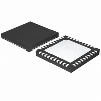
IC TXRX IEEE/ZIGBEE 2.4GHZ 40QFN
Manufacturer
Microchip Technology
Specifications of MRF24J40-I/ML
Package / Case
40-QFN
Frequency
2.4GHz
Data Rate - Maximum
250kbps
Modulation Or Protocol
802.15.4
Applications
ISM, ZigBee™
Power - Output
0dBm
Sensitivity
-95dBm
Voltage - Supply
2.4 V ~ 3.6 V
Current - Receiving
18mA
Current - Transmitting
18mA
Data Interface
PCB, Surface Mount
Antenna Connector
PCB, Surface Mount
Operating Temperature
-40°C ~ 85°C
Number Of Receivers
1
Number Of Transmitters
1
Wireless Frequency
2.4 GHz
Interface Type
4 Wire SPI
Noise Figure
8 dB
Output Power
+ 0 dBm
Operating Supply Voltage
2.5 V, 3.3 V
Maximum Operating Temperature
85 C
Mounting Style
SMD/SMT
Maximum Supply Current
22 mA
Minimum Operating Temperature
- 40 C
Lead Free Status / RoHS Status
Lead free / RoHS Compliant
Memory Size
-
Lead Free Status / Rohs Status
Lead free / RoHS Compliant
Available stocks
Company
Part Number
Manufacturer
Quantity
Price
Company:

Part Number:
MRF24J40-I/ML
Manufacturer:
MICROCHIP
Quantity:
12 000
Part Number:
MRF24J40-I/ML
Manufacturer:
MICROCHIP/微芯
Quantity:
20 000


3.17.3
To encrypt an upper layer frame, perform the following
steps:
1.
FIGURE 3-23:
2.
3.
4.
5.
© 2010 Microchip Technology Inc.
TX FIFO
The host microcontroller loads the TXNFIFO
with the upper layer frame for encryption into the
TXNFIFO
Figure 3-23. The header length field indicates
the number of octets (bytes) that is not
encrypted.
The host microcontroller loads the 13-byte
NONCE value into the UPNONCE12 through
UPNONCE0 (0x240 through 0x24C) registers.
Program the 128-bit security key into the TX
Normal FIFO Security Key FIFO memory
address, 0x280 through 0x28F.
Select the security suite and program the
TXNCIPHER (SECCON0 0x2C<2:0>) bits. The
security suite selection values are shown in
Table 3-24.
Enable Upper Layer Security Encryption mode by
setting the UPENC (SECCR2 0x37<6>) bit = 1.
UPPER LAYER ENCRYPTION
Header
Upper Layer
Length
Encryption
(m)
1
using
(m + n)
Length
Frame
UPPER LAYER ENCRYPTION AND DECRYPTION FORMAT
1
the
format
Security Header
Upper Layer
Header
Header
m
m
shown
in
Preliminary
6.
7.
8.
Note:
Encrypt the frame by setting the TXNTRIG
(TXNCON 0x1B<0>) bit and TXNSECEN
(TXNCON 0x1B<1>) to 1.
A TXNIF (INTSTAT 0x31<0>) interrupt will be
issued. The TXNSTAT (TXSTAT 0x24<0>) bit = 0
indicates the encryption has completed.
The encrypted frame is available in the
TXNFIFO and can be read by the host
microcontroller.
Application Hint: The encryption can be
checked by decrypting the frame data (refer
Section 3.17.4 “Upper Layer Decryption” )
and comparing it to the original frame data.
The header length field, as implemented in
the MRF24J40, is 5 bits long. Therefore,
the header length maximum value is
31 octets (bytes). This conforms to the
IEEE 802.15.4-2003 Specification. How-
ever,
IEEE 802.15.4-2006 Standard. The work
around is to:
- Use a header length no longer than
- Implement a security algorithm in the
Encrypted Payload
31 octets (bytes)
upper layers
Data Payload
Upper Layer
n
n
it
does
MRF24J40
not
DS39776C-page 131
conform
to
octets
octets
the
Related parts for MRF24J40-I/ML
Image
Part Number
Description
Manufacturer
Datasheet
Request
R

Part Number:
Description:
IEEE 802.15.4� 2.4 GHz RF Transceiver
Manufacturer:
MICROCHIP [Microchip Technology]
Datasheet:

Part Number:
Description:
Ieee 802.15.4? 2.4 Ghz Rf Transceiver
Manufacturer:
Microchip Technology Inc.
Datasheet:
Part Number:
Description:
Manufacturer:
Microchip Technology Inc.
Datasheet:
Part Number:
Description:
Manufacturer:
Microchip Technology Inc.
Datasheet:
Part Number:
Description:
Manufacturer:
Microchip Technology Inc.
Datasheet:
Part Number:
Description:
Manufacturer:
Microchip Technology Inc.
Datasheet:
Part Number:
Description:
Manufacturer:
Microchip Technology Inc.
Datasheet:
Part Number:
Description:
Manufacturer:
Microchip Technology Inc.
Datasheet:
Part Number:
Description:
Manufacturer:
Microchip Technology Inc.
Datasheet:
Part Number:
Description:
Manufacturer:
Microchip Technology Inc.
Datasheet: