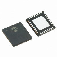
MRF89XA-I/MQ Microchip Technology, MRF89XA-I/MQ Datasheet - Page 89

MRF89XA-I/MQ
Manufacturer Part Number
MRF89XA-I/MQ
Description
TXRX ISM SUB-GHZ ULP 32QFN
Manufacturer
Microchip Technology
Specifications of MRF89XA-I/MQ
Package / Case
32-WFQFN Exposed Pad
Frequency
863MHz ~ 870MHz, 902MHz ~ 928MHz, 950MHz ~ 960MHz
Data Rate - Maximum
200kbps
Modulation Or Protocol
FSK, OOK
Applications
ISM
Power - Output
12.5dBm
Sensitivity
-113dBm
Voltage - Supply
2.1 V ~ 3.6 V
Current - Receiving
3mA
Current - Transmitting
25mA
Data Interface
PCB, Surface Mount
Antenna Connector
PCB, Surface Mount
Operating Temperature
-40°C ~ 85°C
Number Of Receivers
1
Number Of Transmitters
1
Wireless Frequency
863 MHz to 870 MHz, 902 MHz to 928 MHz, 950 MHz to 960 MHz
Interface Type
SPI
Noise Figure
- 112 dBc
Output Power
- 8.5 dBm, + 12.5 dBm
Operating Supply Voltage
2.1 V to 3.6 V
Maximum Operating Temperature
+ 85 C
Mounting Style
SMD/SMT
Maximum Data Rate
256 Kbps
Maximum Supply Current
25 mA
Minimum Operating Temperature
- 40 C
Modulation
FSK
Lead Free Status / RoHS Status
Lead free / RoHS Compliant
Memory Size
-
Lead Free Status / Rohs Status
Lead free / RoHS Compliant
Available stocks
Company
Part Number
Manufacturer
Quantity
Price
Company:
Part Number:
MRF89XA-I/MQ
Manufacturer:
MICROCHIP
Quantity:
12 000
3.11.3.3
Address filtering can be enabled through the
ADDFIL<1:0> bits (PKTCREG<2:1>). It adds another
level of filtering above Sync word, which is typically
useful in multi-node networks where a network ID is
shared between all nodes (Sync word) and each node
has its own ID (address).
Three address based filtering options are available:
• ADDFIL = 01: Received address field is com-
• ADDFIL = 10: Received address field is com-
• ADDFIL = 11: Received address field is com-
FIGURE 3-28:
© 2010 Microchip Technology Inc.
pared with the internal register, NADDSREG. If
they match, the packet is accepted and
processed; otherwise, it is discarded.
pared with the internal register, NADDSREG, and
the constant 0x00. If either is a match, the
received packet is accepted and processed; oth-
erwise, it is discarded. This additional check with
a constant is useful for implementing broadcast in
multi-node networks.
pared with the internal register, NADDSREG, and
the constants 0x00 and 0xFF. If any of the three
matches, the received packet is accepted and
processed, otherwise it is discarded. These addi-
tional checks with constants are useful for
implementing broadcast commands of all nodes.
Here the received address byte, as part of the pay-
load, is not stripped off the packet and is made
available in the FIFO. In addition, NADDSREG
and ADDFIL<1:0> bits from PKTCREG only apply
to RX. On TX side, if address filtering is expected,
the address byte should be put into the FIFO like
any other byte of the payload.
data input
Address Based
X 15
CRC POLYNOMIAL IMPLEMENTATION
X 14
X 13
X 12
CRC Polynomial =X 16 + X 12 + X 5 + 1
Preliminary
X 11
3.11.3.4
The CRC check is enabled by setting the CHKCRCEN
bit (PKTCREG<3>). This bit is used for checking the
integrity of the message. A 16-bit CRC checksum is
calculated on the payload part of the packet and is
appended to the end of the transmitted message. The
CRC checksum is calculated on the received payload
and compared to the transmitted CRC. The result of the
comparison
(PKTCREG<0> and an interrupt can also be generated
on IRQ1.
• On the TX side a two byte CRC checksum is cal-
• On the RX side the checksum is calculated on the
By default, if the CRC check fails, the FIFO is automat-
ically cleared and no interrupt is generated. This filter-
ing function can be disabled through the ACFCRC bit
(FCRCREG<7>) and in this case, even if CRC fails, the
FIFO is not cleared and only the PLREADY (for more
information, refer to Register 2-14) interrupt goes high.
In both the cases, the two CRC checksum bytes are
stripped off by the packet handler and only the payload
is made available in the FIFO.
The CRC is based on the CCITT polynomial as illus-
trated in Figure 3-28. This implementation also detects
errors due to leading and trailing zeros.
* * *
culated on the payload part of the packet and
appended to the end of the message.
received payload and compared with the two
checksum bytes received. The result of the com-
parison is stored in the STSCRCEN bit from and
the CRCOK IRQ source (refer to Register 2-14 for
details).
X 5
CRC-Based
is
stored
X 4
in
MRF89XA
the
* * *
DS70622B-page 89
STSCRCEN
X 0
bit


