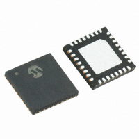
MRF89XA-I/MQ Microchip Technology, MRF89XA-I/MQ Datasheet - Page 72

MRF89XA-I/MQ
Manufacturer Part Number
MRF89XA-I/MQ
Description
TXRX ISM SUB-GHZ ULP 32QFN
Manufacturer
Microchip Technology
Specifications of MRF89XA-I/MQ
Package / Case
32-WFQFN Exposed Pad
Frequency
863MHz ~ 870MHz, 902MHz ~ 928MHz, 950MHz ~ 960MHz
Data Rate - Maximum
200kbps
Modulation Or Protocol
FSK, OOK
Applications
ISM
Power - Output
12.5dBm
Sensitivity
-113dBm
Voltage - Supply
2.1 V ~ 3.6 V
Current - Receiving
3mA
Current - Transmitting
25mA
Data Interface
PCB, Surface Mount
Antenna Connector
PCB, Surface Mount
Operating Temperature
-40°C ~ 85°C
Number Of Receivers
1
Number Of Transmitters
1
Wireless Frequency
863 MHz to 870 MHz, 902 MHz to 928 MHz, 950 MHz to 960 MHz
Interface Type
SPI
Noise Figure
- 112 dBc
Output Power
- 8.5 dBm, + 12.5 dBm
Operating Supply Voltage
2.1 V to 3.6 V
Maximum Operating Temperature
+ 85 C
Mounting Style
SMD/SMT
Maximum Data Rate
256 Kbps
Maximum Supply Current
25 mA
Minimum Operating Temperature
- 40 C
Modulation
FSK
Lead Free Status / RoHS Status
Lead free / RoHS Compliant
Memory Size
-
Lead Free Status / Rohs Status
Lead free / RoHS Compliant
Available stocks
Company
Part Number
Manufacturer
Quantity
Price
Company:
Part Number:
MRF89XA-I/MQ
Manufacturer:
MICROCHIP
Quantity:
12 000
3.4.10.2
A sudden drop in signal strength can cause the bit error
rate to increase. For applications, where the expected
signal drop can be estimated, the OOK demodulator
parameters set by the OOKTHSV<2:0> and OOK-
THPV<2:0>
OOKCREG<4:2>) can be optimized.
For a given number of threshold decrements per bit,
specified by OOKTHPV<2:0>:
• 000
• 001
• 010
• 011
• 100
• 101
• 110
• 111
For each decrement of value from OOKTHSV<2:0>
bits:
• 000
• 001
• 010
• 011
• 100
• 101
• 110
• 111
DS70622B-page 72
MRF89XA
once in each chip period (default)
once in 2 chip periods
once in 4 chip periods
once in 8 chip periods
twice in each chip period
4 times in each chip period
8 times in each chip period
16 times in each chip period
0.5 dB (default)
1.0 dB
1.5 dB
2.0 dB
3.0 dB
4.0 dB
5.0 dB
6.0 dB
Optimizing OOK Demodulator
Response for Fast Fading Signals
bits
(OOKCREG<7:5>
and
Preliminary
3.4.10.3
In addition to the Peak OOK threshold mode, the user
can alternatively select other two types of threshold
detectors:
• Fixed threshold: The value is selected through the
• Average threshold: Data supplied by the RSSI
In Equation 3-14, the higher cut-off frequency enables
a sequence of up to eight consecutive ‘0’s or ‘1’s to be
supported, while the lower cut-off frequency presented
in Equation 3-15 allows for the correct reception of up
to 32 consecutive ‘0’s or ‘1’s.
EQUATION 3-14:
EQUATION 3-15:
OOKCREG register (for more information, refer to
Section 3.4.10.1 “Optimizing the Floor Thresh-
old”).
block is averaged with the cut-off frequency.
OOKATHC<1:0>
OOKATHC<1:0>
Alternative OOK Demodulator
Threshold Modes
=
=
00
© 2010 Microchip Technology Inc.
11
⇒
⇒
f
cutoff
f
cutoff
=
=
BRVAL<6:0>
--------------------------------- -
BRVAL<6:0>
--------------------------------- -
8 π
32 π
•
•


