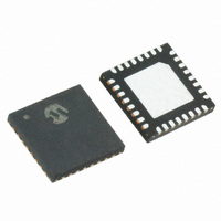
MRF89XA-I/MQ Microchip Technology, MRF89XA-I/MQ Datasheet - Page 16

MRF89XA-I/MQ
Manufacturer Part Number
MRF89XA-I/MQ
Description
TXRX ISM SUB-GHZ ULP 32QFN
Manufacturer
Microchip Technology
Specifications of MRF89XA-I/MQ
Package / Case
32-WFQFN Exposed Pad
Frequency
863MHz ~ 870MHz, 902MHz ~ 928MHz, 950MHz ~ 960MHz
Data Rate - Maximum
200kbps
Modulation Or Protocol
FSK, OOK
Applications
ISM
Power - Output
12.5dBm
Sensitivity
-113dBm
Voltage - Supply
2.1 V ~ 3.6 V
Current - Receiving
3mA
Current - Transmitting
25mA
Data Interface
PCB, Surface Mount
Antenna Connector
PCB, Surface Mount
Operating Temperature
-40°C ~ 85°C
Number Of Receivers
1
Number Of Transmitters
1
Wireless Frequency
863 MHz to 870 MHz, 902 MHz to 928 MHz, 950 MHz to 960 MHz
Interface Type
SPI
Noise Figure
- 112 dBc
Output Power
- 8.5 dBm, + 12.5 dBm
Operating Supply Voltage
2.1 V to 3.6 V
Maximum Operating Temperature
+ 85 C
Mounting Style
SMD/SMT
Maximum Data Rate
256 Kbps
Maximum Supply Current
25 mA
Minimum Operating Temperature
- 40 C
Modulation
FSK
Lead Free Status / RoHS Status
Lead free / RoHS Compliant
Memory Size
-
Lead Free Status / Rohs Status
Lead free / RoHS Compliant
Available stocks
Company
Part Number
Manufacturer
Quantity
Price
Company:
Part Number:
MRF89XA-I/MQ
Manufacturer:
MICROCHIP
Quantity:
12 000
2.4.4
Following the LNA and first down-conversion, there is
an IF amplifier whose gain can be programmed from
-13.5 dB to 0 dB in 4.5 dB steps, through the register
DMODREG
MODULATION
DETAILS”.The default setting corresponds to 0 dB
gain, but lower values can be used to increase the
RSSI dynamic range.
2.4.5
The second mixer stages are followed by the channel
select filters. The channel select filters have a strong
influence on the noise bandwidth and selectivity of the
receiver and therefore, its sensitivity. Each channel
select filter features a passive second-order RC filter,
with a programmable bandwidth and the “fine” channel
selection is performed by an active, third-order,
Butterworth filter, which acts as a low-pass filter for the
zero-IF configuration (FSK), or a complex polyphase
filter for the low-IF (OOK) configuration. For more
information on configuring passive and active filters
see Section 3.4.4 “Channel Filters”.
FIGURE 2-4:
2.5.1
The MRF89XA has an internal, integrated oscillator
circuit and the OSC1 and OSC2 pins are used to
connect to an external crystal resonator. The crystal
oscillator provides the reference frequency for the PLL.
The crystal oscillator circuit, with the required loading
capacitors, provides a 12.8 MHz reference signal for
the PLL. The PLL then generates the local oscillator
frequency. It is possible to “pull” the crystal to the
accurate frequency by changing the load capacitor
value. The crystal oscillator load capacitance is
typically 15 pF, which allows the crystal oscillator circuit
to accept a wide range of crystals.
DS70622B-page 16
MRF89XA
OSC1
MRF89XA
IF GAIN AND SECOND I/Q MIXER
CHANNEL FILTERS
REFERENCE OSCILLATOR PINS
(OSC1/OSC2)
XO
Section 2.14.2
CONFIGURATION
FREQUENCY SYNTHESIZER BLOCK DIAGRAM
OSC2
÷(Ri + 1)
“DATA
F
COMP
REGISTER
PFD
AND
Preliminary
2.5
The frequency synthesizer of the MRF89XA is a fully
integrated integer-N type PLL. The crystal oscillator
provides the reference frequency for the PLL. The PLL
circuit requires only a minimum of five external
components for the PLL loop filter and the VCO tank
circuit.
Figure 2-4 illustrates a block schematic of the
MRF89XA PLL. Here the crystal reference frequency
and the software controlled dividers R, P and S blocks
determine the output frequency of the PLL.
The VCO tank inductors are connected on an external
differential input. Similarly, the loop filter is also located
externally.
An external reference input, such as an oscillator, can
be connected as a reference source. The oscillator can
be connected through a 0.01 µF capacitor if required.
Choosing a higher tolerance crystal results in a lower
TX to RX frequency offset and the ability to select a
smaller deviation in baseband bandwidth. Therefore,
the recommended crystal accuracy should be ≤ 40 ppm.
The guidelines for selecting the appropriate crystal with
specifications are explained in Section 4.6 “Crystal
Specification and Selection Guidelines”.
Note:
÷ 75 * (Pi + 1) + Si
PLLP
Frequency Synthesizer Block
Crystal frequency error will directly trans-
late to carrier frequency (F
frequency deviation error.
Vtune
PLLN
© 2010 Microchip Technology Inc.
VCOTN
VCOTP
rf
VCORS
), bit rate and
LO


