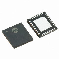
MRF89XA-I/MQ Microchip Technology, MRF89XA-I/MQ Datasheet - Page 69

MRF89XA-I/MQ
Manufacturer Part Number
MRF89XA-I/MQ
Description
TXRX ISM SUB-GHZ ULP 32QFN
Manufacturer
Microchip Technology
Specifications of MRF89XA-I/MQ
Package / Case
32-WFQFN Exposed Pad
Frequency
863MHz ~ 870MHz, 902MHz ~ 928MHz, 950MHz ~ 960MHz
Data Rate - Maximum
200kbps
Modulation Or Protocol
FSK, OOK
Applications
ISM
Power - Output
12.5dBm
Sensitivity
-113dBm
Voltage - Supply
2.1 V ~ 3.6 V
Current - Receiving
3mA
Current - Transmitting
25mA
Data Interface
PCB, Surface Mount
Antenna Connector
PCB, Surface Mount
Operating Temperature
-40°C ~ 85°C
Number Of Receivers
1
Number Of Transmitters
1
Wireless Frequency
863 MHz to 870 MHz, 902 MHz to 928 MHz, 950 MHz to 960 MHz
Interface Type
SPI
Noise Figure
- 112 dBc
Output Power
- 8.5 dBm, + 12.5 dBm
Operating Supply Voltage
2.1 V to 3.6 V
Maximum Operating Temperature
+ 85 C
Mounting Style
SMD/SMT
Maximum Data Rate
256 Kbps
Maximum Supply Current
25 mA
Minimum Operating Temperature
- 40 C
Modulation
FSK
Lead Free Status / RoHS Status
Lead free / RoHS Compliant
Memory Size
-
Lead Free Status / Rohs Status
Lead free / RoHS Compliant
Available stocks
Company
Part Number
Manufacturer
Quantity
Price
Company:
Part Number:
MRF89XA-I/MQ
Manufacturer:
MICROCHIP
Quantity:
12 000
3.4.7.3
The dynamic range of the RSSI is more than 70 dB,
extending from the nominal sensitivity level. The IF
gain, set by the IFGAIN<1:0> bits (DMODREG<1:0>),
is used to achieve this dynamic range.
FIGURE 3-9:
3.4.7.4
The MRF89XA can be used to detect a RSSI level
above a preconfigured threshold. The threshold is set
using RTIVAL<7:0> bits (RSTHIREG<7:0>) and the
IRQ status stored in the RIRQS bit (FTPRIREG<2>),
which is cleared by writing a ‘1’.
FIGURE 3-10:
© 2010 Microchip Technology Inc.
180
160
140
120
100
80
60
40
20
0
-120
RSSIVAL<7:0>
Dynamic Range
RSSI IRQ Source
RIRQS
RSSI DYNAMIC RANGE
RSSI IRQ TIMINGS
-100
24
IF_Gain = 00
26
27
-80
30
IF_Gain = 01
25
RSSI Response
Preliminary
20
Pin [dBm]
20
-60
Clear interrupt
The RSSI response versus the input signal is indepen-
dent of the receiver filter bandwidth. However, in the
absence of any input signal, the minimum value directly
reflects upon the noise floor of the receiver, which is
dependant on the filter bandwidth of the receiver.
Figure 3-9 illustrates the RSSI Dynamic Range
Response.
An interrupt can be mapped to the IRQ0 or IRQ1 pins
through the IRQ0RXS<1:0> and IRQ1RXS<1:0> bits
(FTXRXIREG<7:6>
Figure 3-10 illustrates the timing diagram of the RSSI
interrupt
(RSTHIREG<7:0>) set to ‘11100’.
20
IF_Gain = 10
18
source,
22
-40
33
IF_Gain = 11
20
with
and
22
the
MRF89XA
-20
34
FTXRXIREG<5:4>).
RTIVAL<7:0>
33
DS70622B-page 69
0
bits


