DVK-PRM112 Laird Technologies, DVK-PRM112 Datasheet - Page 7
DVK-PRM112
Manufacturer Part Number
DVK-PRM112
Description
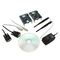
KIT FOR PRM112
Manufacturer
Laird Technologies
Series
FlexRF™r
Type
Transceiver, FHSSr
Specifications of DVK-PRM112
Frequency
2.4GHz
Output Power
50 mW
Antenna
U.FL Coaxial
Silicon Manufacturer
Laird Technologies
Kit Application Type
Communication & Networking
Application Sub Type
RF Module
Kit Contents
2x RF Module, 2x Adapter Board, CD, 2x AC Power Adapters, 2x DB9
Rohs Compliant
Yes
For Use With/related Products
PRM112
Lead Free Status / RoHS Status
Lead free / RoHS Compliant
Lead Free Status / RoHS Status
Lead free / RoHS Compliant, Lead free / RoHS Compliant
Available stocks
Company
Part Number
Manufacturer
Quantity
Price
Company:

Part Number:
DVK-PRM112
Manufacturer:
LAIRD
Quantity:
2


LT2510
Wireless Module
SPECIFICATIONS
4
www.lairdtech.com
TABLE 2: PIN DEFINITIONS FOR THE LT2510 TRANSCEIVER
* Pin 18 (GIO_8) on board revisions 0050-00203 Rev 0 and 0050-00196 rev 2 (and below) is internally not connected.
• All I/O is 3.3V TTL.
• All inputs are weakly pulled High via a 20kOhm pull-up resistor and may be left floating during normal operation
• Minimum Connections: VCC, VPA, GND, TXD, & RXD
• Signal direction is with respect to the transceiver
• Unused pins should be left disconnected
SMT PIN
1
2
3
4
5
6
7
8
9
10
11
12
13
14
15
16
17
18
19
20
21
22
This pin is unavailable as a GPIO on these boards.
ENGINEER’S TIP
PLUGGABLE
PIN
7
6
8
17
19
3
2
10
1
-
-
9
14
5
11
15
16
12
18
13
4
20
TYPE
GND
PWR
PWR
GND
O
O
O
O
O
O
O
I
I
I
I
I
I
I
SIGNAL NAME
CMD/Data
μP_Reset
In Range
GIO_0
GIO_1
GIO_2
GIO_3
GIO_4
GIO_8
GIO_5
GIO_6
GIO_7
Force
9600
DNC
GND
GND
RXD
TXD
Vpa
CTS
Vcc
RTS
Note: Because this mode disables some modes of operation, it should not be
command data. When logic High, the transceiver interprets OEM Host data
Request to Send. Floats high if left unconnected. When enabled in EEPROM,
Force 9600 – When pulled logic Low and then applying power or resetting,
unconnected. After a stable power-on reset, a logic Low pulse will reset the
the module will not transmit data out the Serial UART unless the pin is Low
high when the input buffer reaches the CTS On threshold until the buffer
When logic Low, the transceiver interprets incoming OEM Host data as
When logic Low, the client is in range and synchronized with a server.
Clear to Send - CTS is used for hardware flow control. CTS will toggle
the transceiver’s serial interface is forced to a 9600, 8-N-1 rate.
RESET – Controlled by the LT2510 for power-on reset if left
Asynchronous serial data output from transceiver
permanently pulled Low during normal operation.
3.3 - 3.6 V ±50mV ripple (must be connected)
3.3 - 3.6 V ±50mV ripple (must be connected)
Asynchronous serial data input to transceiver
Reserved for future use. Do not connect.
Reserved for future use. Do not connect.
This will always be Low on a Server.
Generic Output/Hop_Frame
recedes below CTS Off.
Analog to Digital Input
RS-485 Driver Enable
as transmit data.
Do not connect.
Generic Output
Generic Input*
Signal Ground
Signal Ground
Generic Input
PWM Output
FUNCTIONS
transceiver.
Laird Technologies
Related parts for DVK-PRM112
Image
Part Number
Description
Manufacturer
Datasheet
Request
R

Part Number:
Description:
BLUETOOTH EVAL BOARD BTM511
Manufacturer:
Laird Technologies
Datasheet:

Part Number:
Description:
Bluetooth / 802.15.1 Modules & Development Tools BLUETTH AT Data MODLE, No ANT DEVKIT
Manufacturer:
Laird Technologies
Part Number:
Description:
Bluetooth / 802.15.1 Modules & Development Tools BLUETTH Multimed MODLE, No ANT DEVKIT
Manufacturer:
Laird Technologies
Datasheet:

Part Number:
Description:
BLUETOOTH MODULE DEVELOPMENT KIT
Manufacturer:
Laird Technologies
Part Number:
Description:
Bluetooth 2.0 AT Data Module, Internal Antenna Development Kit
Manufacturer:
Laird Technologies

Part Number:
Description:
BT MM DEV KIT
Manufacturer:
Laird Technologies
Datasheet:
Part Number:
Description:
Bluetooth / 802.15.1 Modules & Development Tools BLUETTH HCI Data MDLE INTRNLANT DVKIT
Manufacturer:
Laird Technologies
Datasheet:
Part Number:
Description:
Bluetooth / 802.15.1 Modules & Development Tools BLUETTHMultimedMODLE Plus No Ant DEVKIT
Manufacturer:
Laird Technologies
Part Number:
Description:
Bluetooth / 802.15.1 Modules & Development Tools BLUETTH HCI Data MDLE No ANT DVKIT
Manufacturer:
Laird Technologies
Datasheet:

Part Number:
Description:
KIT FOR PRM113
Manufacturer:
Laird Technologies
Datasheet:

Part Number:
Description:
DEV KIT PRM122
Manufacturer:
Laird Technologies
Datasheet:
Part Number:
Description:
DEV KIT PRM123
Manufacturer:
Laird Technologies
Datasheet:
Part Number:
Description:
DEV KIT PRM121
Manufacturer:
Laird Technologies
Datasheet:

Part Number:
Description:
KIT DEVELOPMENT FOR LT2510 U.FL
Manufacturer:
Laird Technologies
Datasheet:

Part Number:
Description:
Bluetooth / 802.15.1 Modules Class2 v2.1+EDR Kit AT Data, Int Ant,SSP
Manufacturer:
Laird Technologies Wireless M2M
Datasheet: