DVK-PRM112 Laird Technologies, DVK-PRM112 Datasheet - Page 19
DVK-PRM112
Manufacturer Part Number
DVK-PRM112
Description
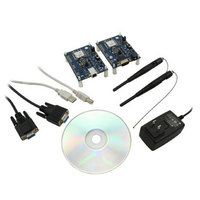
KIT FOR PRM112
Manufacturer
Laird Technologies
Series
FlexRF™r
Type
Transceiver, FHSSr
Specifications of DVK-PRM112
Frequency
2.4GHz
Output Power
50 mW
Antenna
U.FL Coaxial
Silicon Manufacturer
Laird Technologies
Kit Application Type
Communication & Networking
Application Sub Type
RF Module
Kit Contents
2x RF Module, 2x Adapter Board, CD, 2x AC Power Adapters, 2x DB9
Rohs Compliant
Yes
For Use With/related Products
PRM112
Lead Free Status / RoHS Status
Lead free / RoHS Compliant
Lead Free Status / RoHS Status
Lead free / RoHS Compliant, Lead free / RoHS Compliant
Available stocks
Company
Part Number
Manufacturer
Quantity
Price
Company:

Part Number:
DVK-PRM112
Manufacturer:
LAIRD
Quantity:
2


LT2510
Wireless Module
THEORY OF
OPERATION
16 www.lairdtech.com
Vendor ID
The Vendor ID, like the System ID, can be used to uniquely identify a network. Radios with the Vendor ID set, will
only communicate with other radios with the same set Vendor ID.
The Vendor ID is a protected EEPROM parameter and it’s value cannot be read. It can only be written once. OEMs
should be aware that improperly setting the Vendor ID can cause communication issues. Setting the Vendor ID to an
unknown setting will effectively render the radio unable to communicate in a network.
Note: The Vendor ID is a one-time write parameter and it cannot be read.
RSSI
Received Signal Strength Indicator (RSSI) is available to the OEM through a number of means. AT Commands such
as Bin Analyzer and Report RSSI will report RSSI, API Packets for Received and Send Data Complete will report RSSI
and one of three pins can be configured to provide a PWM output representing the RSSI. By default, all of these
commands, except PWM Output represent RSSI as that is a hexadecimal 2’s complement form. Legacy RSSI (detailed
above) can be enabled to provide the RSSI in a non 2’s complement form from 0x00 (very weak signal) to 0xFF (very
strong signal). The control commands for PWM output utilize a Legacy RSSI format from 0x00 to 0xFF.
The RSSI values reported can be converted to a decibel value with the following formulas:
For Non-Legacy values where the RSSI in Hexadecimal ranges from 0x80 to 0x7F:
For Legacy RSSI the equation is:
RSSI_Dec is the reported value represented in Decimal notation
RSSI_Offset = 82
Reported RSSI values are meant as estimate and have an accuracy of +/- 2dBm. The RSSI reported by various
commands has an effective range of -25dBm to -95dBm, outside of this range, the accuracy is not maintained.
Remote I/O Mode (Address 0x57, bit 3)
Remote I/O Mode allows GPIOs on two radios to be joined together so their states will be reflected on the other
radio. Enabling Remote I/O Mode will allow the local radio to transmit its GPIO states whenever there is a change.
The states will be transmitted to the radio specified by the Destination Address (or as a Broadcast if Broadcast mode
is enabled). State information will only be transmitted when there is a change on one of the enabled Digital Inputs.
The states will be retransmitted up to the number of specified Utility Retries (Address 0x4E). Any changes to the
Digital Inputs that occur while a Utility retransmission is occurring will not be transmitted unless the change persists
until all Utility retries have been sent or an acknowledge was received. Therefore, this feature should only be used
for slow-moving changes that occur less than the time it takes to expend all retries. Remote I/O is disabled when the
Force 9600 pin is set at boot.
Remote I/O control lines occur in pairs, with the Digital Input on the local radio driving a Digital Output on the
remote radio and vice-versa. This makes Remote I/O useful for both point to point and point to multipoint networks.
Multipoint to point networks will not benefit from using a single pair of lines as the central point won’t be able to
tell where the line change was sourced. Multiple control lines are available though, so up to four pairs of lines can
be used simultaneously. Likewise, analog inputs can be used (Address 0x57, bit 4) as the input (with a PWM output
on the remote radio), though analog states will only be transmitted when a Utility packet is sent, which are only
triggered by the change of a Digital Input. Threshold settings are not available on analog Inputs.
Output lines will be initialized at boot according to Remote I/O Status (Address 0xC9-0xCA) for the Digital lines and
PWM_Init (Address 0xC8) for the PWM output.
Which control lines are used in Remote I/O is set by the Remote I/O Control bit field (Address 0x60). Note, TxD/RxD
is one pair of Remote I/O lines available. If this pair is used, the module will not respond to Commands and will not
be able to transmit or receive serial data. If this pair is enabled, Force 9600 must be Low at boot to disable Remote
I/O if serial communications are desired.
If this value is greater than or equal to 128, then:
If this value is less than 128, then:
RSSI_dBm = (RSSI_Dec - 256)/2 - RSSI_Offset
RSSI_dBm = (RSSI_Dec)/2 - RSSI_Offset Where,
RSSI_dBm = (RSSI_Dec - 128)/2 -RSSI_Offset
Laird Technologies
Related parts for DVK-PRM112
Image
Part Number
Description
Manufacturer
Datasheet
Request
R

Part Number:
Description:
BLUETOOTH EVAL BOARD BTM511
Manufacturer:
Laird Technologies
Datasheet:

Part Number:
Description:
Bluetooth / 802.15.1 Modules & Development Tools BLUETTH AT Data MODLE, No ANT DEVKIT
Manufacturer:
Laird Technologies
Part Number:
Description:
Bluetooth / 802.15.1 Modules & Development Tools BLUETTH Multimed MODLE, No ANT DEVKIT
Manufacturer:
Laird Technologies
Datasheet:

Part Number:
Description:
BLUETOOTH MODULE DEVELOPMENT KIT
Manufacturer:
Laird Technologies
Part Number:
Description:
Bluetooth 2.0 AT Data Module, Internal Antenna Development Kit
Manufacturer:
Laird Technologies

Part Number:
Description:
BT MM DEV KIT
Manufacturer:
Laird Technologies
Datasheet:
Part Number:
Description:
Bluetooth / 802.15.1 Modules & Development Tools BLUETTH HCI Data MDLE INTRNLANT DVKIT
Manufacturer:
Laird Technologies
Datasheet:
Part Number:
Description:
Bluetooth / 802.15.1 Modules & Development Tools BLUETTHMultimedMODLE Plus No Ant DEVKIT
Manufacturer:
Laird Technologies
Part Number:
Description:
Bluetooth / 802.15.1 Modules & Development Tools BLUETTH HCI Data MDLE No ANT DVKIT
Manufacturer:
Laird Technologies
Datasheet:

Part Number:
Description:
KIT FOR PRM113
Manufacturer:
Laird Technologies
Datasheet:

Part Number:
Description:
DEV KIT PRM122
Manufacturer:
Laird Technologies
Datasheet:
Part Number:
Description:
DEV KIT PRM123
Manufacturer:
Laird Technologies
Datasheet:
Part Number:
Description:
DEV KIT PRM121
Manufacturer:
Laird Technologies
Datasheet:

Part Number:
Description:
KIT DEVELOPMENT FOR LT2510 U.FL
Manufacturer:
Laird Technologies
Datasheet:

Part Number:
Description:
Bluetooth / 802.15.1 Modules Class2 v2.1+EDR Kit AT Data, Int Ant,SSP
Manufacturer:
Laird Technologies Wireless M2M
Datasheet: