DVK-PRM112 Laird Technologies, DVK-PRM112 Datasheet - Page 18
DVK-PRM112
Manufacturer Part Number
DVK-PRM112
Description
KIT FOR PRM112
Manufacturer
Laird Technologies
Series
FlexRF™r
Type
Transceiver, FHSSr
Specifications of DVK-PRM112
Frequency
2.4GHz
Output Power
50 mW
Antenna
U.FL Coaxial
Silicon Manufacturer
Laird Technologies
Kit Application Type
Communication & Networking
Application Sub Type
RF Module
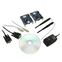
Kit Contents
2x RF Module, 2x Adapter Board, CD, 2x AC Power Adapters, 2x DB9
Rohs Compliant
Yes
For Use With/related Products
PRM112
Lead Free Status / RoHS Status
Lead free / RoHS Compliant
Lead Free Status / RoHS Status
Lead free / RoHS Compliant, Lead free / RoHS Compliant
Available stocks
Company
Part Number
Manufacturer
Quantity
Price
Company:

Part Number:
DVK-PRM112
Manufacturer:
LAIRD
Quantity:
2


LT2510
Wireless Module
THEORY OF
OPERATION
15 www.lairdtech.com
Sniff Permit (EEPROM 0x45, bit 0)
Sniff Permit will allow a radio to receive a data packet from another radio on the network regardless of the
Destination MAC Address in the packet. This allows an OEM to create a Sniffer for all network traffic. Sniff Permit
would need to be enabled on the transmitting radio, to grant it’s permission to be heard. Sniff Report and Sniff
Permit would need to be enabled on the sniffer radio, to cause it to send sniffed packets out the serial port.
RSSI Output to PWM
A moving RSSI Average can be written to the PWM Output as a signal strength indicator. The output pin to use, the
threshold range for the RSSI and the RSSI Type reported can all be configured through EEPROM Addresses.
The PWM Output has a 315.077uS period. The duty cycle is set by the RSSI value recorded by the transceiver and the
RSSI Threshold High and RSSI Threshold Low values
RSSI Threshold High (EEPROM 0x65)
Is the upper limit of the recorded RSSI reading. RSSI Values reported above this value (strong signals) will report a
100% Duty Cycle on the PWM Output.
RSSI Threshold Low (EEPROM 0x66)
Is the lower limit of the recorded RSSI reading. RSSI Values reported below this value (weak signals) will report a 0%
Duty Cycle on the PWM Output.
To calculate the thresholds use the equation:
Then convert this from Decimal to Hexadecimal notation.
RSSI_Lag (EEPROM 0x67)
Controls a filter on the PWM output to smooth out the changes made to the PWM signal. Setting the value to
a very Low number will result in very quick changing output. Setting the value to a higher number will result in a
slower varying PWM output. Setting the value to 0x00 will result in an instantaneous RSSI. Because RSSI is measured
per hop and the radio can hop over 43 or 79 hops, instantaneous RSSI may be too quickly moving to be of use as a
signal strength indicator. The default value is 0x40 and should be sufficient for most applications. It should be set to
a value of less than 0x80.
RSSI_Lag affects the PWM Output according to the following equations:
Cumulative_Lag is then stored in memory until the next time RSSI is calculated.
If (Cumulative_Lag mod EE_Lag) > 0, then Cumulative_Lag = remainder of (Cumulative_Lag mod EE_Lag)
RSSI_Control (EEPROM 0x68):
RSSI Control is a bitfield used to control the output of the RSSI PWM output and what messages the radio reports
on. Note if Disable Hop Frame is Disabled (so as to report Hop Frame), it will be output on GO_0 (pin 1 of SMT
module), so the PWM Output should not be set to output to that pin or conflicting signals will be sent on that
output pin.
Address 0x68, Bit
Bit 0 set
Bit 1 set
Bit 2 set
Bit 3 set
Bit 4 set
Bit 5 set
Bit 6 clear, Bit 7 clear
Bit 6 set, Bit 7 clear
RSSI_Dec = (RSSI_dBm + 82) * 2 +128
Cumulative_Lag = Cumulative_Lag + (RSSI_Current – Old_RSSI_Avg)
New_RSSI_Avg = Old_RSSI_Avg + (Cumulative_Lag mod EE_Lag)
Input
GIO_4
GIO_8*
GIO_7
CMD/Data
RTS
RXD
All I/O are Outputs
All I/O are Inputs
Output
GIO_0
GIO_1
GIO_3
GIO_2
CTS
TXD
Laird Technologies
Related parts for DVK-PRM112
Image
Part Number
Description
Manufacturer
Datasheet
Request
R

Part Number:
Description:
BLUETOOTH EVAL BOARD BTM511
Manufacturer:
Laird Technologies
Datasheet:

Part Number:
Description:
Bluetooth / 802.15.1 Modules & Development Tools BLUETTH AT Data MODLE, No ANT DEVKIT
Manufacturer:
Laird Technologies
Part Number:
Description:
Bluetooth / 802.15.1 Modules & Development Tools BLUETTH Multimed MODLE, No ANT DEVKIT
Manufacturer:
Laird Technologies
Datasheet:

Part Number:
Description:
BLUETOOTH MODULE DEVELOPMENT KIT
Manufacturer:
Laird Technologies
Part Number:
Description:
Bluetooth 2.0 AT Data Module, Internal Antenna Development Kit
Manufacturer:
Laird Technologies

Part Number:
Description:
BT MM DEV KIT
Manufacturer:
Laird Technologies
Datasheet:
Part Number:
Description:
Bluetooth / 802.15.1 Modules & Development Tools BLUETTH HCI Data MDLE INTRNLANT DVKIT
Manufacturer:
Laird Technologies
Datasheet:
Part Number:
Description:
Bluetooth / 802.15.1 Modules & Development Tools BLUETTHMultimedMODLE Plus No Ant DEVKIT
Manufacturer:
Laird Technologies
Part Number:
Description:
Bluetooth / 802.15.1 Modules & Development Tools BLUETTH HCI Data MDLE No ANT DVKIT
Manufacturer:
Laird Technologies
Datasheet:

Part Number:
Description:
KIT FOR PRM113
Manufacturer:
Laird Technologies
Datasheet:

Part Number:
Description:
DEV KIT PRM122
Manufacturer:
Laird Technologies
Datasheet:
Part Number:
Description:
DEV KIT PRM123
Manufacturer:
Laird Technologies
Datasheet:
Part Number:
Description:
DEV KIT PRM121
Manufacturer:
Laird Technologies
Datasheet:

Part Number:
Description:
KIT DEVELOPMENT FOR LT2510 U.FL
Manufacturer:
Laird Technologies
Datasheet:

Part Number:
Description:
Bluetooth / 802.15.1 Modules Class2 v2.1+EDR Kit AT Data, Int Ant,SSP
Manufacturer:
Laird Technologies Wireless M2M
Datasheet: