DVK-PRM112 Laird Technologies, DVK-PRM112 Datasheet - Page 34
DVK-PRM112
Manufacturer Part Number
DVK-PRM112
Description
KIT FOR PRM112
Manufacturer
Laird Technologies
Series
FlexRF™r
Type
Transceiver, FHSSr
Specifications of DVK-PRM112
Frequency
2.4GHz
Output Power
50 mW
Antenna
U.FL Coaxial
Silicon Manufacturer
Laird Technologies
Kit Application Type
Communication & Networking
Application Sub Type
RF Module
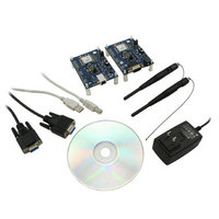
Kit Contents
2x RF Module, 2x Adapter Board, CD, 2x AC Power Adapters, 2x DB9
Rohs Compliant
Yes
For Use With/related Products
PRM112
Lead Free Status / RoHS Status
Lead free / RoHS Compliant
Lead Free Status / RoHS Status
Lead free / RoHS Compliant, Lead free / RoHS Compliant
Available stocks
Company
Part Number
Manufacturer
Quantity
Price
Company:

Part Number:
DVK-PRM112
Manufacturer:
LAIRD
Quantity:
2


LT2510
Wireless Module
CONFIGURING
THE LT2510
31 www.lairdtech.com
COMMAND DESCRIPTIONS
Read API Control
The OEM Host issues this command to read the API
Control byte.
Write API Control
The OEM Host issues this command to write the API
Control byte to enable or disable the API features.
Read Digital Inputs
The OEM Host issues this command to read the state of
both digital output lines.
Read ADC
The OEM host issues this command to read the analog
to digital converters at up to 12-bit resolution. Higher
resolutions can cause slower responses from the
command. The time required for a conversion is:
Tconv = (decimation rate + 16) * 0.23uS.
In most applications this will be used to measure the
input voltage (to detect reduced battery power) with
Vcc/3, the temperature sensor or the Analog input
pin. For the most accurate results the 1.25V internal
reference should be chosen, though this would limit
the OEM to a maximum A/D Input of 1.25V. Vcc/3 and
the temperature sensor readings should use the internal
1.25v reference as those voltages will never exceed 1.25v.
The ADC result is represented in a two’s complement
form. The result is the difference between ground and
the selected channel and will be a value between -2048
and 2047 with 2047 representing the maximum value
where the ADC result equals the reference voltage and
-2048 equals the negative of the reference voltage.
The ADC cannot measure a voltage higher than the
reference voltage.
Get Last RSSI
This command is used to report signal strength (RSSI)
information from the last RF Packet the radio received.
This command will report the signal strength of any
received RF packet including the Server beacon, data
packets and even RF Packets that were not intended for
this radio (eg: packets with a different Destination MAC
Address than this radio).
Command:
Number of Bytes Returned:
Response:
Parameter Range:
<Auto Dest> = bits 7-3: 0
Command:
Number of Bytes Returned:
Response:
Parameter Range:
<Digital Out>
Command:
Number of Bytes Returned:
Response:
Parameter Range:
<Data bits 7-6> = <Reference Voltage>
<Data bits 5-4>= <Resolution>
<Data bits 3-0>= <Channel>
<Hi ADC> = MSB or requested 12-bit ADC value
<Lo ADC> = LSB of requested 12-bit ADC value
Command:
Number of Bytes Returned:
Response:
Parameter Range:
<RSSI>: 0x00 – 0xFF
Command:
Number of Bytes Returned:
Response:
Parameter Range:
<Auto Dest> = bits 7-3: 0
00: Internal 1.25V reference
10: Voltage on Vcc pin
00: 64 decimation rate (7 bits resolution)
01: 128 decimation rate (9 bits resolution)
10: 256 decimation rate (10 bits resolution)
11: 512 decimation rate (12 bits resolution)
0000: AD/In (GIO_7)
1100: GND
1101: Positive Voltage Reference
1110: Temperature Sensor
1111: Vcc/3
<0xCC> <API Control>
0xCC <Digital Out>
0xCC <Hi ADC> <Lo ADC>
<0xCC> <RSSI>
<0xCC> <API Control>
<0xCC> <0x17> <API Control>
<0xCC> <0x20>
<0xCC> <0x21> <Data>
<0xCC> <0x22>
<0xCC> <0x16>
= bit-1: GIO_8
= bit-0: GIO_4
bit-2: Send Data Complete
bit-1: Transmit API
bit-0: Receive API
bit-2: Send Data Complete
bit-1: Transmit API
bit-0: Receive API
2
2
3
2
2
Laird Technologies
Related parts for DVK-PRM112
Image
Part Number
Description
Manufacturer
Datasheet
Request
R

Part Number:
Description:
BLUETOOTH EVAL BOARD BTM511
Manufacturer:
Laird Technologies
Datasheet:

Part Number:
Description:
Bluetooth / 802.15.1 Modules & Development Tools BLUETTH AT Data MODLE, No ANT DEVKIT
Manufacturer:
Laird Technologies
Part Number:
Description:
Bluetooth / 802.15.1 Modules & Development Tools BLUETTH Multimed MODLE, No ANT DEVKIT
Manufacturer:
Laird Technologies
Datasheet:

Part Number:
Description:
BLUETOOTH MODULE DEVELOPMENT KIT
Manufacturer:
Laird Technologies
Part Number:
Description:
Bluetooth 2.0 AT Data Module, Internal Antenna Development Kit
Manufacturer:
Laird Technologies

Part Number:
Description:
BT MM DEV KIT
Manufacturer:
Laird Technologies
Datasheet:
Part Number:
Description:
Bluetooth / 802.15.1 Modules & Development Tools BLUETTH HCI Data MDLE INTRNLANT DVKIT
Manufacturer:
Laird Technologies
Datasheet:
Part Number:
Description:
Bluetooth / 802.15.1 Modules & Development Tools BLUETTHMultimedMODLE Plus No Ant DEVKIT
Manufacturer:
Laird Technologies
Part Number:
Description:
Bluetooth / 802.15.1 Modules & Development Tools BLUETTH HCI Data MDLE No ANT DVKIT
Manufacturer:
Laird Technologies
Datasheet:

Part Number:
Description:
KIT FOR PRM113
Manufacturer:
Laird Technologies
Datasheet:

Part Number:
Description:
DEV KIT PRM122
Manufacturer:
Laird Technologies
Datasheet:
Part Number:
Description:
DEV KIT PRM123
Manufacturer:
Laird Technologies
Datasheet:
Part Number:
Description:
DEV KIT PRM121
Manufacturer:
Laird Technologies
Datasheet:

Part Number:
Description:
KIT DEVELOPMENT FOR LT2510 U.FL
Manufacturer:
Laird Technologies
Datasheet:

Part Number:
Description:
Bluetooth / 802.15.1 Modules Class2 v2.1+EDR Kit AT Data, Int Ant,SSP
Manufacturer:
Laird Technologies Wireless M2M
Datasheet: