DVK-PRM112 Laird Technologies, DVK-PRM112 Datasheet - Page 14
DVK-PRM112
Manufacturer Part Number
DVK-PRM112
Description
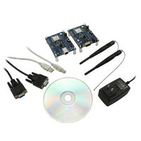
KIT FOR PRM112
Manufacturer
Laird Technologies
Series
FlexRF™r
Type
Transceiver, FHSSr
Specifications of DVK-PRM112
Frequency
2.4GHz
Output Power
50 mW
Antenna
U.FL Coaxial
Silicon Manufacturer
Laird Technologies
Kit Application Type
Communication & Networking
Application Sub Type
RF Module
Kit Contents
2x RF Module, 2x Adapter Board, CD, 2x AC Power Adapters, 2x DB9
Rohs Compliant
Yes
For Use With/related Products
PRM112
Lead Free Status / RoHS Status
Lead free / RoHS Compliant
Lead Free Status / RoHS Status
Lead free / RoHS Compliant, Lead free / RoHS Compliant
Available stocks
Company
Part Number
Manufacturer
Quantity
Price
Company:

Part Number:
DVK-PRM112
Manufacturer:
LAIRD
Quantity:
2


LT2510
Wireless Module
THEORY OF
OPERATION
11 www.lairdtech.com
RF Packet Size
RF Packet Size is used in conjunction with Interface Timeout to determine when to delineate incoming data as
an entire packet based on whichever condition is met first. When the transceiver receives the number of bytes
specified by RF Packet Size (EEPROM address 0x5A) without experiencing a byte gap equal to Interface Timeout,
that block of data is processed as a complete packet. Every packet the transceiver sends over the RF contains extra
header bytes not counted in the RF Packet Size. Therefore, it is much more efficient to send a few large packets
than to send many short packets. The maximum RF Packet Size is 239 bytes, or 0xEF, at 500kkbps RF Data Rate and
96 bytes, or 0x60, at 280kbps RF Data Rate.
The RF Packet Size in Address 0x5A will not be used if Auto Config (Address 0x56, bit 0) is enabled. The default
for the RF Data Rate will be used instead. The RF Packet Size should not be set to less than 0x07, to ensure AT
commands can still be issued.
RF Packet Size is also used by the radio to determine the number of data slots per hop. In order to efficiently
transmit data across the RF the radio will automatically add more data slots to the hop to correspond to a smaller RF
Packet size. The number of slots per hop is given in the table below.
RS-485 Data Enable
The Timing of the DE-RE pin will vary depending on the Interface Baud Rate selected. Prior to firmware v2.2, these
parameters are set automatically if Auto Config is enabled. If Auto Config is Disabled, these values must be set
correctly, even if RS-485 Data Enable is not being used. In v2.2 and beyond these parameters are not controlled by
Auto Config, but instead by Address 0x57, bit 5.
The values to set are: 485_Delay_H: Address 0x49
485_Delay_M: Address 0x4A
485_Delay_L: Address 0x4B
To set them, use the equation (round the result up):
Address 0x49 and 0x4A: 485H/M = 8.125MHz / (81*Baud_Rate), quotient only
Address 0x4B: 485L = (8.125MHz / Baud_Rate) mod 81
So for 19,200 you should calculate 00 05 12
RF Data Rate
280kbps
280kbps
280kbps
500kbps
500kbps
500kbps
500kbps
500kbps
• The more slots per hop, the less likely that retries will occur on a new frequency, this may reduce the
• Idle current consumption will increase as more slots are added.
• You need to use the same number of slots for every radio on the network.
• Full duplex still only reserves the first slot for the Server. If there are 6 slots, the first slot is reserved for the
ENGINEER’S TIP
effectiveness of the module as a Frequency Hopping radio.
Server to transmit and the remainder is shared by the Clients.
RF Packet Size
0x01 – 0x09
0x0A – 0x25
0x26-0x60
0x01 – 0x0C
0x0D – 0x25
0x026 – 0x47
0x48 – 0x7D
0x7E – 0xEF
Number of Data Slots
4 slots
3 slots
2 slots
6 slots
5 slots
4 slots
3 slots
2 slots
Laird Technologies
Related parts for DVK-PRM112
Image
Part Number
Description
Manufacturer
Datasheet
Request
R

Part Number:
Description:
BLUETOOTH EVAL BOARD BTM511
Manufacturer:
Laird Technologies
Datasheet:

Part Number:
Description:
Bluetooth / 802.15.1 Modules & Development Tools BLUETTH AT Data MODLE, No ANT DEVKIT
Manufacturer:
Laird Technologies
Part Number:
Description:
Bluetooth / 802.15.1 Modules & Development Tools BLUETTH Multimed MODLE, No ANT DEVKIT
Manufacturer:
Laird Technologies
Datasheet:

Part Number:
Description:
BLUETOOTH MODULE DEVELOPMENT KIT
Manufacturer:
Laird Technologies
Part Number:
Description:
Bluetooth 2.0 AT Data Module, Internal Antenna Development Kit
Manufacturer:
Laird Technologies

Part Number:
Description:
BT MM DEV KIT
Manufacturer:
Laird Technologies
Datasheet:
Part Number:
Description:
Bluetooth / 802.15.1 Modules & Development Tools BLUETTH HCI Data MDLE INTRNLANT DVKIT
Manufacturer:
Laird Technologies
Datasheet:
Part Number:
Description:
Bluetooth / 802.15.1 Modules & Development Tools BLUETTHMultimedMODLE Plus No Ant DEVKIT
Manufacturer:
Laird Technologies
Part Number:
Description:
Bluetooth / 802.15.1 Modules & Development Tools BLUETTH HCI Data MDLE No ANT DVKIT
Manufacturer:
Laird Technologies
Datasheet:

Part Number:
Description:
KIT FOR PRM113
Manufacturer:
Laird Technologies
Datasheet:

Part Number:
Description:
DEV KIT PRM122
Manufacturer:
Laird Technologies
Datasheet:
Part Number:
Description:
DEV KIT PRM123
Manufacturer:
Laird Technologies
Datasheet:
Part Number:
Description:
DEV KIT PRM121
Manufacturer:
Laird Technologies
Datasheet:

Part Number:
Description:
KIT DEVELOPMENT FOR LT2510 U.FL
Manufacturer:
Laird Technologies
Datasheet:

Part Number:
Description:
Bluetooth / 802.15.1 Modules Class2 v2.1+EDR Kit AT Data, Int Ant,SSP
Manufacturer:
Laird Technologies Wireless M2M
Datasheet: